-
Part Symbol
-
Footprint
-
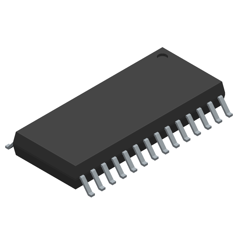
3D Model
Available Download Formats
By downloading CAD models, you agree to our Terms & Conditions and Privacy Policy

Buffer/Inverter Based Peripheral Driver, 4 Driver, 15A, MOS, PDSO28, GREEN, PLASTIC, 28 PIN
Tip: Data for a part may vary between manufacturers. You can filter for manufacturers on the top of the page next to the part image and part number.
BTM7740G by Infineon Technologies AG is a Peripheral Driver.
Peripheral Drivers are under the broader part category of Drivers And Interfaces.
A driver controls the current or voltage delivered to components like LCDs or motors, while an interface component connects systems for data transfer and control. Read more about Drivers And Interfaces on our Drivers And Interfaces part category page.
| Part # | Distributor | Description | Stock | Price | Buy | |
|---|---|---|---|---|---|---|
|
|
LCSC | MOSFET 8V18V SOIC-28 Gate Drivers ROHS | 1000 |
|
$3.8181 / $5.5173 | Buy Now |
|
|
Win Source Electronics | Motor Driver Automotive 28-Pin DSO / IC BRIDGE DRIVER PAR 28DSO | 7200 |
|
$11.0487 / $14.2700 | Buy Now |
By downloading CAD models, you agree to our Terms & Conditions and Privacy Policy
|
|
BTM7740G
Infineon Technologies AG
Buy Now
Datasheet
|
Compare Parts:
BTM7740G
Infineon Technologies AG
Buffer/Inverter Based Peripheral Driver, 4 Driver, 15A, MOS, PDSO28, GREEN, PLASTIC, 28 PIN
|
| Pbfree Code | Yes | |
| Rohs Code | Yes | |
| Part Life Cycle Code | Obsolete | |
| Ihs Manufacturer | INFINEON TECHNOLOGIES AG | |
| Part Package Code | SOIC | |
| Package Description | GREEN, PLASTIC, 28 PIN | |
| Pin Count | 28 | |
| Reach Compliance Code | compliant | |
| ECCN Code | EAR99 | |
| HTS Code | 8542.39.00.01 | |
| Samacsys Manufacturer | Infineon | |
| Driver Number of Bits | 4 | |
| Interface IC Type | BUFFER OR INVERTER BASED PERIPHERAL DRIVER | |
| JESD-30 Code | R-PDSO-G28 | |
| Moisture Sensitivity Level | 3 | |
| Number of Terminals | 28 | |
| Output Current Flow Direction | SOURCE AND SINK | |
| Output Peak Current Limit-Nom | 15 A | |
| Package Body Material | PLASTIC/EPOXY | |
| Package Code | SOP | |
| Package Equivalence Code | SOP28,.4 | |
| Package Shape | RECTANGULAR | |
| Package Style | SMALL OUTLINE | |
| Peak Reflow Temperature (Cel) | NOT SPECIFIED | |
| Qualification Status | Not Qualified | |
| Screening Level | AEC-Q100 | |
| Surface Mount | YES | |
| Technology | MOS | |
| Terminal Form | GULL WING | |
| Terminal Pitch | 1.27 mm | |
| Terminal Position | DUAL | |
| Time@Peak Reflow Temperature-Max (s) | NOT SPECIFIED |
A 2-layer or 4-layer PCB with a solid ground plane and thermal vias is recommended. The device should be placed near a heat sink or a thermal pad to ensure good heat dissipation.
Ensure proper heat sinking, use a thermal interface material (TIM) with a thermal conductivity of at least 1 W/mK, and follow the recommended PCB layout guidelines. Also, consider using a thermocouple to monitor the device temperature.
The maximum allowed voltage on the input pins is 5.5V, but it's recommended to keep it below 5V to ensure reliable operation and prevent damage to the device.
Use ESD protection devices such as TVS diodes or ESD arrays on the input lines, and ensure that the PCB design follows ESD protection guidelines. Also, handle the device with an ESD wrist strap or mat to prevent damage during assembly.
The recommended soldering profile is a peak temperature of 260°C, with a dwell time of 30-60 seconds above 217°C. Use a solder with a melting point of 217°C or higher.