-
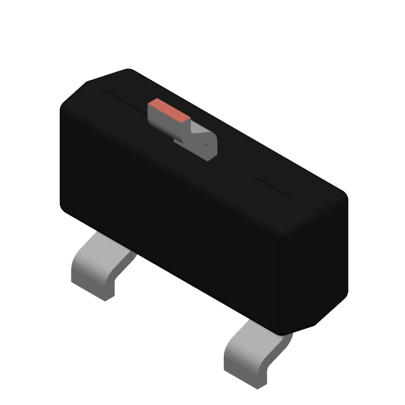
3D Model
Available Download Formats
By downloading CAD models, you agree to our Terms & Conditions and Privacy Policy

BCW60 series - NPN general purpose transistors@en-us TO-236 3-Pin
Tip: Data for a part may vary between manufacturers. You can filter for manufacturers on the top of the page next to the part image and part number.
BCW60B,235 by Nexperia is a Small Signal Bipolar Transistor.
Small Signal Bipolar Transistors are under the broader part category of Transistors.
A transistor is a small semiconductor device used to amplify, control, or create electrical signals. When selecting a transistor, factors such as voltage, current rating, gain, and power dissipation must be considered, with common types. Read more about Transistors on our Transistors part category page.
| Part # | Distributor | Description | Stock | Price | Buy | |
|---|---|---|---|---|---|---|
|
DISTI #
BCW60B,235-ND
|
DigiKey | TRANS NPN 32V 0.1A TO-236AB Min Qty: 10000 Lead time: 8 Weeks Container: Tape & Reel (TR) | Temporarily Out of Stock |
|
$0.0230 / $0.0345 | Buy Now |
|
DISTI #
BCW60B,235
|
Avnet Americas | Trans GP BJT NPN 32V 0.1A 3-Pin TO-236AB T/R - Tape and Reel (Alt: BCW60B,235) RoHS: Compliant Min Qty: 40000 Package Multiple: 10000 Lead time: 8 Weeks, 0 Days Container: Reel | 0 |
|
$0.0278 / $0.0284 | Buy Now |
|
DISTI #
771-BCW60B235
|
Mouser Electronics | Bipolar Transistors - BJT NPN general purpose transistor RoHS: Compliant | 0 |
|
$0.0230 / $0.2400 | Order Now |
|
DISTI #
BCW60B,235
|
Avnet Silica | Trans GP BJT NPN 32V 01A 3Pin TO236AB TR (Alt: BCW60B,235) RoHS: Compliant Min Qty: 10000 Package Multiple: 10000 Lead time: 10 Weeks, 0 Days | Silica - 0 |
|
Buy Now |
By downloading CAD models, you agree to our Terms & Conditions and Privacy Policy
|
|
BCW60B,235
Nexperia
Buy Now
Datasheet
|
Compare Parts:
BCW60B,235
Nexperia
BCW60 series - NPN general purpose transistors@en-us TO-236 3-Pin
|
| Rohs Code | Yes | |
| Part Life Cycle Code | Active | |
| Ihs Manufacturer | NEXPERIA | |
| Part Package Code | TO-236 | |
| Pin Count | 3 | |
| Manufacturer Package Code | SOT23 | |
| Reach Compliance Code | compliant | |
| ECCN Code | EAR99 | |
| Factory Lead Time | 8 Weeks | |
| Date Of Intro | 1993-03-01 | |
| Samacsys Manufacturer | Nexperia | |
| Additional Feature | LOW NOISE | |
| Collector Current-Max (IC) | 0.2 A | |
| Collector-Emitter Voltage-Max | 32 V | |
| Configuration | SINGLE | |
| DC Current Gain-Min (hFE) | 70 | |
| JESD-30 Code | R-PDSO-G3 | |
| JESD-609 Code | e3 | |
| Moisture Sensitivity Level | 1 | |
| Number of Elements | 1 | |
| Number of Terminals | 3 | |
| Operating Temperature-Max | 150 °C | |
| Package Body Material | PLASTIC/EPOXY | |
| Package Shape | RECTANGULAR | |
| Package Style | SMALL OUTLINE | |
| Peak Reflow Temperature (Cel) | 260 | |
| Polarity/Channel Type | NPN | |
| Qualification Status | Not Qualified | |
| Surface Mount | YES | |
| Terminal Finish | TIN | |
| Terminal Form | GULL WING | |
| Terminal Position | DUAL | |
| Time@Peak Reflow Temperature-Max (s) | 30 | |
| Transistor Application | SWITCHING | |
| Transistor Element Material | SILICON | |
| Transition Frequency-Nom (fT) | 250 MHz | |
| Turn-off Time-Max (toff) | 800 ns | |
| Turn-on Time-Max (ton) | 150 ns | |
| VCEsat-Max | 0.55 V |
The maximum operating temperature range for BCW60B,235 is -40°C to 150°C, as specified in the datasheet. However, it's recommended to operate within -40°C to 125°C for optimal performance and reliability.
To ensure stability, make sure to follow the recommended layout and component placement guidelines in the datasheet. Additionally, use a suitable output capacitor with a low ESR (Equivalent Series Resistance) and a minimum capacitance of 1 μF to 10 μF, depending on the specific application requirements.
The recommended input capacitor value is 1 μF to 10 μF, with a voltage rating of at least 25 V. A ceramic or film capacitor with a low ESR is recommended, such as X7R or X5R dielectric types.
While BCW60B,235 can handle high currents, it's essential to ensure that the device is properly heat-sinked and that the maximum current rating is not exceeded. The device can handle up to 1 A of output current, but the junction temperature should not exceed 150°C. Consult the datasheet for thermal resistance and power dissipation calculations.
To protect the device from overvoltage and undervoltage conditions, consider adding overvoltage protection (OVP) and undervoltage protection (UVP) circuits. These can be implemented using external components, such as zener diodes, resistors, and capacitors, or by using dedicated protection ICs.