-
Part Symbol
-
Footprint
-
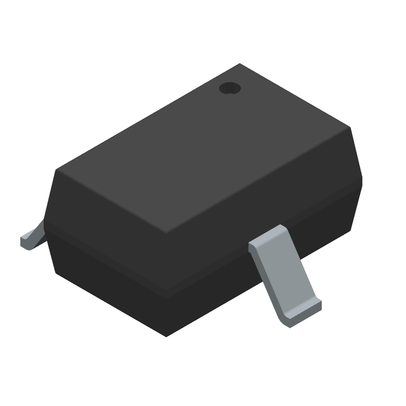
3D Model
Available Download Formats
By downloading CAD models, you agree to our Terms & Conditions and Privacy Policy

Rectifier Diode, 2 Element, 0.2A, 85V V(RRM), Silicon, SOT-323, 3 PIN
Tip: Data for a part may vary between manufacturers. You can filter for manufacturers on the top of the page next to the part image and part number.
BAV99WE6327 by Infineon Technologies AG is a Rectifier Diode.
Rectifier Diodes are under the broader part category of Diodes.
A diode is a electrical part that can control the direction in which the current flows in a device. Consider factors like voltage drop, current capacity, reverse voltage, and operating frequency when selecting a diode. Read more about Diodes on our Diodes part category page.
| Part # | Distributor | Description | Stock | Price | Buy | |
|---|---|---|---|---|---|---|
|
|
Quest Components | 0.2 A, 80 V, 2 ELEMENT, SILICON, SIGNAL DIODE, SOT-323 | 114392 |
|
$0.0225 / $0.1500 | Buy Now |
|
|
Quest Components | 0.2 A, 80 V, 2 ELEMENT, SILICON, SIGNAL DIODE, SOT-323 | 2438 |
|
$0.0270 / $0.0600 | Buy Now |
|
|
ComSIT USA | SILICON SWITCHING DIODE Rectifier Diode, 2 Element, 0.2A, 85V V(RRM), Silicon ECCN: EAR99 RoHS: Not Compliant |
|
|
RFQ |
By downloading CAD models, you agree to our Terms & Conditions and Privacy Policy
|
|
BAV99WE6327
Infineon Technologies AG
Buy Now
Datasheet
|
Compare Parts:
BAV99WE6327
Infineon Technologies AG
Rectifier Diode, 2 Element, 0.2A, 85V V(RRM), Silicon, SOT-323, 3 PIN
|
| Rohs Code | Yes | |
| Part Life Cycle Code | Obsolete | |
| Ihs Manufacturer | INFINEON TECHNOLOGIES AG | |
| Part Package Code | SC-70 | |
| Package Description | SOT-323, 3 PIN | |
| Pin Count | 3 | |
| Manufacturer Package Code | SOT323 | |
| Reach Compliance Code | compliant | |
| ECCN Code | EAR99 | |
| HTS Code | 8541.10.00.70 | |
| Samacsys Manufacturer | Infineon | |
| Application | GENERAL PURPOSE | |
| Configuration | SERIES CONNECTED, CENTER TAP, 2 ELEMENTS | |
| Diode Element Material | SILICON | |
| Diode Type | RECTIFIER DIODE | |
| Forward Voltage-Max (VF) | 0.715 V | |
| JESD-30 Code | R-PDSO-G3 | |
| JESD-609 Code | e3 | |
| Moisture Sensitivity Level | 1 | |
| Non-rep Pk Forward Current-Max | 4.5 A | |
| Number of Elements | 2 | |
| Number of Phases | 1 | |
| Number of Terminals | 3 | |
| Operating Temperature-Max | 150 °C | |
| Output Current-Max | 0.2 A | |
| Package Body Material | PLASTIC/EPOXY | |
| Package Shape | RECTANGULAR | |
| Package Style | SMALL OUTLINE | |
| Peak Reflow Temperature (Cel) | 260 | |
| Power Dissipation-Max | 0.25 W | |
| Qualification Status | Not Qualified | |
| Reference Standard | AEC-Q101 | |
| Rep Pk Reverse Voltage-Max | 85 V | |
| Reverse Recovery Time-Max | 0.004 µs | |
| Surface Mount | YES | |
| Terminal Finish | MATTE TIN | |
| Terminal Form | GULL WING | |
| Terminal Position | DUAL |
Infineon provides a recommended PCB layout in their application note AN191 (Power MOSFETs - Thermal Management) and AN201 (Power MOSFETs - PCB Layout). Following these guidelines can help minimize thermal resistance, reduce parasitic inductance, and ensure optimal performance.
The gate resistor value depends on the specific application, driver circuit, and switching frequency. A general guideline is to choose a value between 10 Ω to 100 Ω. However, it's recommended to consult Infineon's application notes and simulation tools, such as the Gate Resistor Calculator, to determine the optimal value for your specific use case.
Although the datasheet specifies a maximum VGS of ±20 V, it's recommended to limit the voltage to ±15 V during switching to prevent damage to the device. This is because the device may experience voltage overshoots or ringing during high-frequency switching.
To ensure SOA compliance, you should consider the device's voltage, current, and temperature ratings. Use Infineon's SOA simulation tools or consult their application notes to determine the safe operating area for your specific application. Additionally, consider implementing overcurrent and overvoltage protection to prevent device damage.
The recommended storage temperature range for the BAV99WE6327 is -40°C to 150°C. Storing the device within this range can help prevent damage and ensure long-term reliability.