-
Part Symbol
-
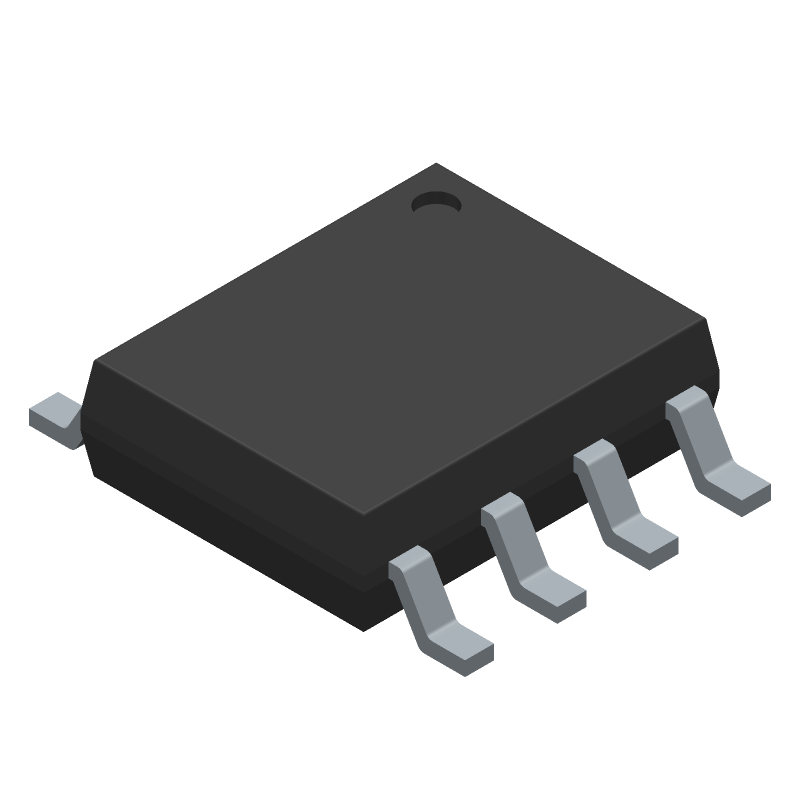
Footprint
-
3D Model
Available Download Formats
By downloading CAD models, you agree to our Terms & Conditions and Privacy Policy

Switching Regulator, Current-mode, 2A, 380kHz Switching Freq-Max, PDSO8, SOP-8
Tip: Data for a part may vary between manufacturers. You can filter for manufacturers on the top of the page next to the part image and part number.
AP6502SP-13 by Diodes Incorporated is a Switching Regulator or Controller.
Switching Regulator or Controllers are under the broader part category of Power Circuits.
A power circuit delivers electricity in order to operate a load for an electronic device. Power circuits include transformers, generators and switches. Read more about Power Circuits on our Power Circuits part category page.
By downloading CAD models, you agree to our Terms & Conditions and Privacy Policy
|
|
AP6502SP-13
Diodes Incorporated
Buy Now
Datasheet
|
Compare Parts:
AP6502SP-13
Diodes Incorporated
Switching Regulator, Current-mode, 2A, 380kHz Switching Freq-Max, PDSO8, SOP-8
|
| Pbfree Code | Yes | |
| Rohs Code | Yes | |
| Part Life Cycle Code | Obsolete | |
| Ihs Manufacturer | DIODES INC | |
| Part Package Code | SOIC | |
| Pin Count | 8 | |
| Reach Compliance Code | compliant | |
| ECCN Code | EAR99 | |
| HTS Code | 8542.39.00.01 | |
| Samacsys Manufacturer | Diodes Incorporated | |
| Additional Feature | OPERATES IN ADJUSTABLE MODE FROM 0.925 TO 20V | |
| Analog IC - Other Type | SWITCHING REGULATOR | |
| Control Mode | CURRENT-MODE | |
| Control Technique | PULSE WIDTH MODULATION | |
| Input Voltage-Max | 23 V | |
| Input Voltage-Min | 4.75 V | |
| Input Voltage-Nom | 12 V | |
| JESD-30 Code | R-PDSO-G8 | |
| JESD-609 Code | e3 | |
| Length | 4.9 mm | |
| Moisture Sensitivity Level | 1 | |
| Number of Functions | 1 | |
| Number of Terminals | 8 | |
| Operating Temperature-Max | 85 °C | |
| Operating Temperature-Min | -40 °C | |
| Output Current-Max | 2 A | |
| Package Body Material | PLASTIC/EPOXY | |
| Package Code | HSOP | |
| Package Equivalence Code | SOP8,.25 | |
| Package Shape | RECTANGULAR | |
| Package Style | SMALL OUTLINE, HEAT SINK/SLUG | |
| Peak Reflow Temperature (Cel) | 260 | |
| Qualification Status | Not Qualified | |
| Seated Height-Max | 1.75 mm | |
| Surface Mount | YES | |
| Switcher Configuration | BUCK | |
| Switching Frequency-Max | 380 kHz | |
| Temperature Grade | INDUSTRIAL | |
| Terminal Finish | MATTE TIN | |
| Terminal Form | GULL WING | |
| Terminal Pitch | 1.27 mm | |
| Terminal Position | DUAL | |
| Time@Peak Reflow Temperature-Max (s) | 30 | |
| Width | 3.9 mm |
This table gives cross-reference parts and alternative options found for AP6502SP-13. The Form Fit Function (FFF) tab will give you the options that are more likely to serve as direct pin-to-pin alternates or drop-in parts. The Functional Equivalents tab will give you options that are likely to match the same function of AP6502SP-13, but it may not fit your design. Always verify details of parts you are evaluating, as these parts are offered as suggestions for what you are looking for and are not guaranteed.
| Part Number | Manufacturer | Composite Price | Description | Compare |
|---|---|---|---|---|
| LSP5527-S8A | Diodes Incorporated | Check for Price | Switching Regulator, Current-mode, 340kHz Switching Freq-Max, PDSO8, | AP6502SP-13 vs LSP5527-S8A |
A good PCB layout for optimal thermal performance would be to have a solid ground plane on the bottom layer, and to use thermal vias to connect the exposed pad to the ground plane. This helps to dissipate heat efficiently.
To ensure stability, make sure to follow the recommended component values and PCB layout guidelines. Additionally, a minimum ESR of 1 ohm for the output capacitor is recommended to prevent oscillation.
Although the datasheet specifies a maximum input voltage of 18V, it's recommended to derate the input voltage to 15V to ensure reliable operation and to prevent damage to the device.
While it's possible to use a different inductor value or type, it's not recommended as it may affect the device's performance and stability. The recommended inductor value and type are specified in the datasheet for optimal performance.
To troubleshoot issues, start by checking the input voltage, output voltage, and current. Verify that the component values and PCB layout match the recommended design. Use an oscilloscope to check for voltage ripple and oscillations. Consult the datasheet and application notes for guidance.