-
Part Symbol
-
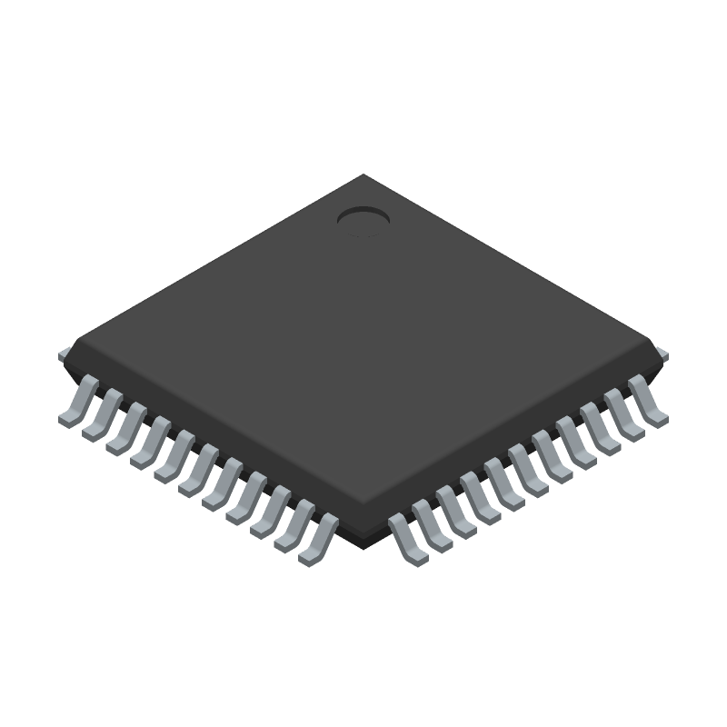
Footprint
-
3D Model
Available Download Formats
By downloading CAD models, you agree to our Terms & Conditions and Privacy Policy

12-Bit R/D Converter with Reference Oscillator
Tip: Data for a part may vary between manufacturers. You can filter for manufacturers on the top of the page next to the part image and part number.
ADW71205WSTZ-RL by Analog Devices Inc is a Position Converter.
Position Converters are under the broader part category of Converters.
A converter is an electrical circuit that transforms electric energy into a different form that will support a elecrical load needed by a device. Read more about Converters on our Converters part category page.
| Part # | Distributor | Description | Stock | Price | Buy | |
|---|---|---|---|---|---|---|
|
DISTI #
505-ADW71205WSTZ-RLCT-ND
|
DigiKey | IC RDC 12BIT 44LQFP Min Qty: 1 Lead time: 10 Weeks Container: Digi-Reel®, Cut Tape (CT), Tape & Reel (TR) |
1226 In Stock |
|
$21.3875 / $32.4800 | Buy Now |
|
DISTI #
584-ADW71205WSTZ-R
|
Mouser Electronics | Data Acquisition ADCs/DACs - Specialized 12-bit, 1000RPS Resolver-Digital Convert RoHS: Compliant | 0 |
|
$21.3900 | Order Now |
|
|
Analog Devices Inc | 12-bit, 1000RPS Resolver-Digit Min Qty: 1 Package Multiple: 1500 | 246 |
|
$16.0100 / $32.4800 | Buy Now |
By downloading CAD models, you agree to our Terms & Conditions and Privacy Policy
|
|
ADW71205WSTZ-RL
Analog Devices Inc
Buy Now
Datasheet
|
Compare Parts:
ADW71205WSTZ-RL
Analog Devices Inc
12-Bit R/D Converter with Reference Oscillator
|
| Pbfree Code | No | |
| Rohs Code | Yes | |
| Part Life Cycle Code | Active | |
| Ihs Manufacturer | ANALOG DEVICES INC | |
| Part Package Code | QFP | |
| Pin Count | 44 | |
| Manufacturer Package Code | ST-44-1 | |
| Reach Compliance Code | compliant | |
| ECCN Code | EAR99 | |
| HTS Code | 8542.39.00.01 | |
| Samacsys Manufacturer | Analog Devices | |
| Analog Input Voltage-Max | 2.3 V | |
| Angular Accuracy-Max | 1 arc min | |
| Converter Type | SYNCHRO OR RESOLVER TO DIGITAL CONVERTER | |
| Moisture Sensitivity Level | 3 | |
| Number of Bits | 16 | |
| Number of Functions | 1 | |
| Peak Reflow Temperature (Cel) | 260 | |
| Screening Level | AEC-Q100 | |
| Signal/Output Frequency | 1000 Hz | |
| Supply Voltage-Nom | 15 V | |
| Time@Peak Reflow Temperature-Max (s) | 30 | |
| Tracking Rate-Max | 18 rps |
A 4-layer PCB with a solid ground plane and a separate analog ground plane is recommended. Keep the analog and digital sections separate, and use a star-grounding configuration to minimize noise.
Follow the calibration procedure outlined in the datasheet, which involves applying a known input voltage and adjusting the internal calibration registers. It's also recommended to perform a system-level calibration to account for external component tolerances.
The maximum allowed input voltage range is ±VREF (typically 2.5V or 5V), but it's recommended to keep the input voltage within ±1.5V to ensure accurate measurements and prevent damage to the device.
Use a low-noise power supply, keep the analog and digital sections separate, and use shielding and filtering to minimize electromagnetic interference. Also, use a low-pass filter on the input signals to reduce high-frequency noise.
The recommended clock frequency is between 1 MHz and 20 MHz, depending on the specific application requirements. A higher clock frequency can improve conversion speed, but may also increase power consumption and noise sensitivity.