-
Part Symbol
-
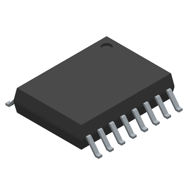
Footprint
-
3D Model
Available Download Formats
By downloading CAD models, you agree to our Terms & Conditions and Privacy Policy

Quad-Channel Digital Isolator (4/0 Channel Directionality)
Tip: Data for a part may vary between manufacturers. You can filter for manufacturers on the top of the page next to the part image and part number.
ADUM1400WSRWZ-RL by Analog Devices Inc is an Other Interface IC.
Other Interface ICs are under the broader part category of Drivers And Interfaces.
A driver controls the current or voltage delivered to components like LCDs or motors, while an interface component connects systems for data transfer and control. Read more about Drivers And Interfaces on our Drivers And Interfaces part category page.
| Part # | Distributor | Description | Stock | Price | Buy | |
|---|---|---|---|---|---|---|
|
DISTI #
505-ADUM1400WSRWZ-RLCT-ND
|
DigiKey | DGTL ISOLTR 2.5KV 4CH GP 16-SOIC Min Qty: 1 Lead time: 10 Weeks Container: Cut Tape (CT), Digi-Reel®, Tape & Reel (TR) |
1000 In Stock |
|
$4.8125 / $10.9000 | Buy Now |
|
DISTI #
584-ADUM1400WSRWZ-RL
|
Mouser Electronics | Digital Isolators 3-5.5V DC 1Mbit/sc 4Chnl Dgtl 4Txr0Rxr RoHS: Compliant | 549 |
|
$4.8100 / $10.8800 | Buy Now |
|
|
Analog Devices Inc | 3-5.5V DC 1Mbit/sc 4Chnl Dgtl Min Qty: 1000 Package Multiple: 1000 | 200 |
|
$4.8125 / $10.3700 | Buy Now |
|
DISTI #
26639497
|
Verical | Digital Isolator CMOS 4-CH 1Mbps 16-Pin SOIC W T/R Automotive AEC-Q100 RoHS: Compliant Min Qty: 1000 Package Multiple: 1000 | Americas - 6000 |
|
$4.7619 | Buy Now |
|
|
Win Source Electronics | IC DGTL ISO 4CH LOGIC 16SOIC | 7440 |
|
$6.4254 / $9.6380 | Buy Now |
By downloading CAD models, you agree to our Terms & Conditions and Privacy Policy
|
|
ADUM1400WSRWZ-RL
Analog Devices Inc
Buy Now
Datasheet
|
Compare Parts:
ADUM1400WSRWZ-RL
Analog Devices Inc
Quad-Channel Digital Isolator (4/0 Channel Directionality)
|
| Pbfree Code | No | |
| Rohs Code | Yes | |
| Part Life Cycle Code | Active | |
| Ihs Manufacturer | ANALOG DEVICES INC | |
| Part Package Code | SOIC | |
| Package Description | SOIC-16 | |
| Pin Count | 16 | |
| Manufacturer Package Code | RW-16 | |
| Reach Compliance Code | compliant | |
| ECCN Code | EAR99 | |
| HTS Code | 8543.70.98.60 | |
| Samacsys Manufacturer | Analog Devices | |
| Interface IC Type | INTERFACE CIRCUIT | |
| JESD-30 Code | R-PDSO-G16 | |
| JESD-609 Code | e3 | |
| Length | 10.3 mm | |
| Moisture Sensitivity Level | 3 | |
| Number of Functions | 4 | |
| Number of Terminals | 16 | |
| Operating Temperature-Max | 125 °C | |
| Operating Temperature-Min | -40 °C | |
| Package Body Material | PLASTIC/EPOXY | |
| Package Code | SOP | |
| Package Shape | RECTANGULAR | |
| Package Style | SMALL OUTLINE | |
| Peak Reflow Temperature (Cel) | 260 | |
| Qualification Status | Not Qualified | |
| Screening Level | AEC-Q100 | |
| Seated Height-Max | 2.65 mm | |
| Supply Voltage-Max | 5.5 V | |
| Supply Voltage-Min | 3 V | |
| Supply Voltage-Nom | 5 V | |
| Surface Mount | YES | |
| Technology | CMOS | |
| Temperature Grade | AUTOMOTIVE | |
| Terminal Finish | Matte Tin (Sn) | |
| Terminal Form | GULL WING | |
| Terminal Pitch | 1.27 mm | |
| Terminal Position | DUAL | |
| Time@Peak Reflow Temperature-Max (s) | 30 | |
| Width | 7.5 mm |
The maximum operating temperature range for the ADUM1400WSRWZ-RL is -40°C to +125°C.
To ensure reliable operation in high-noise environments, it is recommended to use proper PCB layout techniques, such as separating the input and output circuits, using ground planes, and minimizing trace lengths. Additionally, consider using shielding and filtering to reduce electromagnetic interference (EMI).
It is recommended to use a 0.1 μF ceramic capacitor in parallel with a 10 μF electrolytic capacitor for power supply decoupling. This helps to reduce noise and ensure stable operation.
The ADUM1400WSRWZ-RL is designed for low-speed to medium-speed data transmission, up to 25 Mbps. For high-speed data transmission, consider using a different isolator with a higher bandwidth, such as the ADUM1200 or ADUM1300 series.
The output enable (OE) pin is an active-low input that enables or disables the output of the isolator. Connect the OE pin to a logic low (GND) to enable the output, or to a logic high (VCC) to disable the output.