-
Part Symbol
-
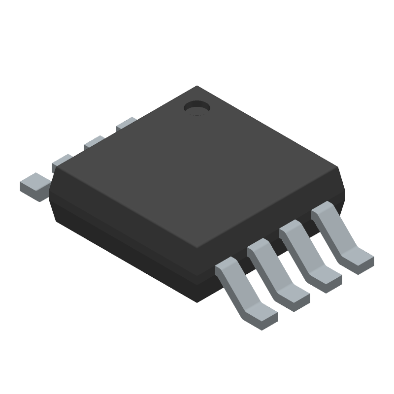
Footprint
-
3D Model
Available Download Formats
By downloading CAD models, you agree to our Terms & Conditions and Privacy Policy
Bidirectional, Zero-Drift, Current Sense Amplifier
Tip: Data for a part may vary between manufacturers. You can filter for manufacturers on the top of the page next to the part image and part number.
AD8418AWHRMZ-RL by Analog Devices Inc is an Operational Amplifier.
Operational Amplifiers are under the broader part category of Amplifier Circuits.
Amplifier circuits use external power to increase the amplitude of an input signal. They can be used to perform linear amplifications or logarithmic functions. Read more about Amplifier Circuits on our Amplifier Circuits part category page.
| Part # | Distributor | Description | Stock | Price | Buy | |
|---|---|---|---|---|---|---|
|
DISTI #
505-AD8418AWHRMZ-RLCT-ND
|
DigiKey | IC CURRENT SENSE 1 CIRCUIT 8MSOP Min Qty: 1 Lead time: 10 Weeks Container: Digi-Reel®, Cut Tape (CT), Tape & Reel (TR) | Temporarily Out of Stock |
|
$2.5125 / $6.4300 | Buy Now |
|
DISTI #
584-AD8418AWHRMZ-RL
|
Mouser Electronics | Current Sense Amplifiers High Common Mode Cur Sense, -3V to 80V RoHS: Compliant | 0 |
|
$2.5700 / $4.9200 | Order Now |
|
|
Analog Devices Inc | High Common Mode Cur Sense, -3 Min Qty: 3000 Package Multiple: 3000 | 0 |
|
$2.5125 / $6.4300 | Buy Now |
|
|
Vyrian | Amplifiers | 3306 |
|
RFQ |
By downloading CAD models, you agree to our Terms & Conditions and Privacy Policy
|
|
AD8418AWHRMZ-RL
Analog Devices Inc
Buy Now
Datasheet
|
Compare Parts:
AD8418AWHRMZ-RL
Analog Devices Inc
Bidirectional, Zero-Drift, Current Sense Amplifier
|
| Pbfree Code | No | |
| Rohs Code | Yes | |
| Part Life Cycle Code | Active | |
| Ihs Manufacturer | ANALOG DEVICES INC | |
| Package Description | MSOP-8 | |
| Pin Count | 8 | |
| Manufacturer Package Code | RM-8 | |
| Reach Compliance Code | compliant | |
| ECCN Code | EAR99 | |
| HTS Code | 8542.33.00.01 | |
| Samacsys Manufacturer | Analog Devices | |
| Amplifier Type | OPERATIONAL AMPLIFIER | |
| Architecture | VOLTAGE-FEEDBACK | |
| Average Bias Current-Max (IIB) | 260 µA | |
| Bandwidth (3dB)-Nom | 0.25 MHz | |
| Common-mode Reject Ratio-Min | 90 dB | |
| Common-mode Reject Ratio-Nom | 100 dB | |
| Frequency Compensation | YES | |
| Input Offset Voltage-Max | 200 µV | |
| JESD-30 Code | S-PDSO-G8 | |
| JESD-609 Code | e3 | |
| Length | 3 mm | |
| Low-Bias | NO | |
| Low-Offset | YES | |
| Micropower | NO | |
| Moisture Sensitivity Level | 1 | |
| Number of Functions | 1 | |
| Number of Terminals | 8 | |
| Operating Temperature-Max | 150 °C | |
| Operating Temperature-Min | -40 °C | |
| Package Body Material | PLASTIC/EPOXY | |
| Package Code | TSSOP | |
| Package Equivalence Code | TSSOP8,.19 | |
| Package Shape | SQUARE | |
| Package Style | SMALL OUTLINE, THIN PROFILE, SHRINK PITCH | |
| Packing Method | TR, 13 INCH | |
| Peak Reflow Temperature (Cel) | 260 | |
| Power | NO | |
| Programmable Power | NO | |
| Screening Level | AEC-Q100 | |
| Seated Height-Max | 1.1 mm | |
| Slew Rate-Nom | 1 V/us | |
| Supply Current-Max | 4.2 mA | |
| Supply Voltage Limit-Max | 6 V | |
| Supply Voltage-Nom (Vsup) | 5 V | |
| Surface Mount | YES | |
| Temperature Grade | AUTOMOTIVE | |
| Terminal Finish | Matte Tin (Sn) | |
| Terminal Form | GULL WING | |
| Terminal Pitch | 0.65 mm | |
| Terminal Position | DUAL | |
| Time@Peak Reflow Temperature-Max (s) | 30 | |
| Wideband | NO | |
| Width | 3 mm |
A good PCB layout for the AD8418 involves keeping the input traces as short as possible, using a solid ground plane, and placing the input capacitors close to the device. Additionally, it's recommended to use a 4-layer PCB with a dedicated analog ground plane to minimize noise and interference.
The AD8418 has an internal calibration circuit that sets the gain and offset of the device. However, for optimal performance, it's recommended to perform an external calibration using an external voltage reference and a precision resistor network to set the gain and offset to the desired values.
The maximum allowed input voltage for the AD8418 is ±25V, but it's recommended to keep the input voltage within ±20V to ensure optimal performance and to prevent damage to the device.
To minimize EMI and RFI interference, it's recommended to use a shielded enclosure, keep the input cables as short as possible, and use twisted pair cables with a shielded drain wire. Additionally, using a common-mode filter or a ferrite bead on the input lines can help to reduce interference.
It's recommended to use a 10uF ceramic capacitor in parallel with a 100nF ceramic capacitor to decouple the power supply. This helps to reduce noise and ripple on the power supply lines and ensures optimal performance of the AD8418.