-
Part Symbol
-
Footprint
Available Download Formats
By downloading CAD models, you agree to our Terms & Conditions and Privacy Policy

16-Bit Parallel 100 kSPS Sampling ADC
Tip: Data for a part may vary between manufacturers. You can filter for manufacturers on the top of the page next to the part image and part number.
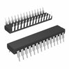
AD676KN by Analog Devices Inc is an Analog to Digital Converter.
Analog to Digital Converters are under the broader part category of Converters.
A converter is an electrical circuit that transforms electric energy into a different form that will support a elecrical load needed by a device. Read more about Converters on our Converters part category page.
By downloading CAD models, you agree to our Terms & Conditions and Privacy Policy
|
|
AD676KN
Analog Devices Inc
Buy Now
Datasheet
|
Compare Parts:
AD676KN
Analog Devices Inc
16-Bit Parallel 100 kSPS Sampling ADC
|
| Pbfree Code | No | |
| Rohs Code | No | |
| Part Life Cycle Code | Obsolete | |
| Ihs Manufacturer | ANALOG DEVICES INC | |
| Part Package Code | DIP | |
| Package Description | PLASTIC, DIP-28 | |
| Pin Count | 28 | |
| Manufacturer Package Code | N-28-2 | |
| Reach Compliance Code | not_compliant | |
| HTS Code | 8542.39.00.01 | |
| Samacsys Manufacturer | Analog Devices | |
| Analog Input Voltage-Max | 10 V | |
| Analog Input Voltage-Min | -10 V | |
| Conversion Time-Max | 1000 µs | |
| Converter Type | ADC, SUCCESSIVE APPROXIMATION | |
| JESD-30 Code | R-PDIP-T28 | |
| JESD-609 Code | e0 | |
| Length | 37.4 mm | |
| Linearity Error-Max (EL) | 0.0015% | |
| Negative Supply Voltage-Nom | -12 V | |
| Number of Analog In Channels | 1 | |
| Number of Bits | 16 | |
| Number of Functions | 1 | |
| Number of Terminals | 28 | |
| Operating Temperature-Max | 70 °C | |
| Operating Temperature-Min | ||
| Output Bit Code | BINARY | |
| Output Format | PARALLEL, WORD | |
| Package Body Material | PLASTIC/EPOXY | |
| Package Code | DIP | |
| Package Equivalence Code | DIP28,.6 | |
| Package Shape | RECTANGULAR | |
| Package Style | IN-LINE | |
| Qualification Status | Not Qualified | |
| Sample Rate | 0.1 MHz | |
| Sample and Hold / Track and Hold | SAMPLE | |
| Seated Height-Max | 6.35 mm | |
| Supply Current-Max | 12 mA | |
| Supply Voltage-Nom | 12 V | |
| Surface Mount | NO | |
| Technology | BIMOS | |
| Temperature Grade | COMMERCIAL | |
| Terminal Finish | TIN LEAD | |
| Terminal Form | THROUGH-HOLE | |
| Terminal Pitch | 2.54 mm | |
| Terminal Position | DUAL | |
| Width | 15.24 mm |
The AD676KN requires careful layout and routing to minimize noise and ensure optimal performance. It is recommended to follow the layout guidelines provided in the datasheet, including keeping the analog and digital grounds separate, using a solid ground plane, and minimizing the length of the input traces. Additionally, it is recommended to use a 4-layer PCB with a dedicated analog power plane and a dedicated digital power plane.
The AD676KN requires calibration to achieve the highest accuracy. The calibration process involves adjusting the internal offset and gain of the device to match the specific application requirements. The calibration process can be done using the AD676KN's built-in calibration registers or through the use of external calibration circuits. It is recommended to follow the calibration procedure outlined in the datasheet and to use high-precision calibration equipment to ensure accurate results.
The AD676KN is specified to operate over a temperature range of -40°C to +85°C. However, it is recommended to operate the device within a temperature range of 0°C to +70°C for optimal performance and reliability. Operating the device outside of this range may affect its accuracy, stability, and reliability.
Yes, the AD676KN can be used in a multi-channel application. The device has a serial interface that allows it to be connected to a microcontroller or other digital device, making it suitable for use in multi-channel applications. However, it is recommended to use a separate AD676KN device for each channel to ensure optimal performance and to minimize crosstalk between channels.
The AD676KN requires proper power supply decoupling to ensure optimal performance and to minimize noise. It is recommended to use a combination of ceramic and electrolytic capacitors to decouple the power supply, with a minimum of 10uF of capacitance per power supply pin. Additionally, it is recommended to use a low-ESR capacitor to decouple the analog power supply.