-
Part Symbol
-
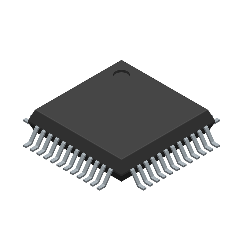
Footprint
-
3D Model
Available Download Formats
By downloading CAD models, you agree to our Terms & Conditions and Privacy Policy

Variable Resolution, 10-Bit to 16-Bit R/D Converter with Reference Oscillator
Tip: Data for a part may vary between manufacturers. You can filter for manufacturers on the top of the page next to the part image and part number.
AD2S1210SST-EP-RL7 by Analog Devices Inc is a Position Converter.
Position Converters are under the broader part category of Converters.
A converter is an electrical circuit that transforms electric energy into a different form that will support a elecrical load needed by a device. Read more about Converters on our Converters part category page.
| Part # | Distributor | Description | Stock | Price | Buy | |
|---|---|---|---|---|---|---|
|
|
Vyrian | Converters | 160 |
|
RFQ |
By downloading CAD models, you agree to our Terms & Conditions and Privacy Policy
|
|
AD2S1210SST-EP-RL7
Analog Devices Inc
Buy Now
Datasheet
|
Compare Parts:
AD2S1210SST-EP-RL7
Analog Devices Inc
Variable Resolution, 10-Bit to 16-Bit R/D Converter with Reference Oscillator
|
| Pbfree Code | No | |
| Rohs Code | No | |
| Part Life Cycle Code | Obsolete | |
| Ihs Manufacturer | ANALOG DEVICES INC | |
| Part Package Code | QFP | |
| Package Description | LFQFP, | |
| Pin Count | 48 | |
| Manufacturer Package Code | ST-48 | |
| Reach Compliance Code | not_compliant | |
| HTS Code | 8542.39.00.01 | |
| Samacsys Manufacturer | Analog Devices | |
| Analog Input Voltage-Max | 2.3 V | |
| Angular Accuracy-Max | 4 arc min | |
| Converter Type | SYNCHRO OR RESOLVER TO DIGITAL CONVERTER | |
| JESD-30 Code | S-XQFP-G48 | |
| JESD-609 Code | e0 | |
| Length | 7 mm | |
| Moisture Sensitivity Level | 3 | |
| Number of Bits | 14 | |
| Number of Functions | 1 | |
| Number of Terminals | 48 | |
| Package Body Material | UNSPECIFIED | |
| Package Code | LFQFP | |
| Package Shape | SQUARE | |
| Package Style | FLATPACK, LOW PROFILE, FINE PITCH | |
| Peak Reflow Temperature (Cel) | 240 | |
| Qualification Status | Not Qualified | |
| Seated Height-Max | 1.6 mm | |
| Signal/Output Frequency | 2600 Hz | |
| Supply Voltage-Nom | 15 V | |
| Surface Mount | YES | |
| Temperature Grade | MILITARY | |
| Terminal Finish | TIN LEAD | |
| Terminal Form | GULL WING | |
| Terminal Pitch | 0.5 mm | |
| Terminal Position | QUAD | |
| Tracking Rate-Max | 18 rps | |
| Width | 7 mm |
A 4-layer PCB with a solid ground plane and a separate analog ground plane is recommended. Keep the analog and digital grounds separate and connect them at a single point. Use a star topology for the power supply and keep the power supply traces away from the analog signals.
Calibration involves adjusting the internal gain and offset of the device to match the specific requirements of your application. Refer to the datasheet for the calibration procedure, and use the ADI-provided calibration software or a third-party calibration tool.
Power up the device in the following sequence: VDD, AVDD, and then DVDD. Ensure that the power supplies are stable and within the recommended voltage range before applying the clock signal.
Use a heat sink or a thermal pad to dissipate heat. Ensure good airflow around the device, and consider using a thermal interface material to improve heat transfer. Follow the recommended thermal design guidelines in the datasheet.
Use ESD protection devices such as TVS diodes or ESD arrays on the input and output pins. Follow proper handling and storage procedures to prevent ESD damage. Use an ESD-protected workstation and wear an ESD strap when handling the device.