-
Part Symbol
-
Footprint
-
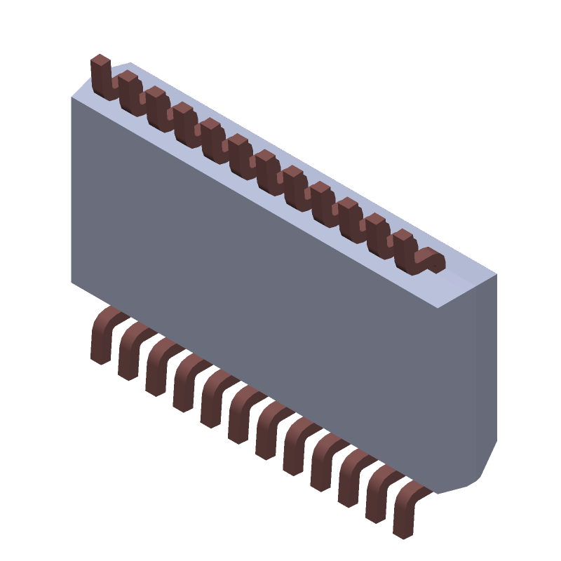
3D Model
Available Download Formats
By downloading CAD models, you agree to our Terms & Conditions and Privacy Policy
Analog Circuit, 1 Func, PDSO24, QSOP-24
Tip: Data for a part may vary between manufacturers. You can filter for manufacturers on the top of the page next to the part image and part number.
ACS709LLFTR-6BB-T by Allegro MicroSystems LLC is an Other Signal Circuit.
Other Signal Circuits are under the broader part category of Signal Circuits.
A signal is an electronic means of transmitting information, either as an analog signal with continuous values or a digital signal with discrete values. Signals are used in various systems and networks. Read more about Signal Circuits on our Signal Circuits part category page.
| Part # | Distributor | Description | Stock | Price | Buy | |
|---|---|---|---|---|---|---|
|
DISTI #
250-709LLFTR6BBT
|
Mouser Electronics | Board Mount Current Sensors For New Designs Contact Factory RoHS: Compliant | 0 |
|
Order Now | |
|
DISTI #
ACS709LLFTR-6BB-T
|
Avnet Silica | HighBandwidth Fast Fault Response Current Sensor IC in Thermally Enhanced Package (Alt: ACS709LLFTR-6BB-T) RoHS: Compliant Min Qty: 7500 Package Multiple: 2500 | Silica - 0 |
|
Buy Now |
By downloading CAD models, you agree to our Terms & Conditions and Privacy Policy
|
|
ACS709LLFTR-6BB-T
Allegro MicroSystems LLC
Buy Now
Datasheet
|
Compare Parts:
ACS709LLFTR-6BB-T
Allegro MicroSystems LLC
Analog Circuit, 1 Func, PDSO24, QSOP-24
|
| Rohs Code | Yes | |
| Part Life Cycle Code | Active | |
| Ihs Manufacturer | ALLEGRO MICROSYSTEMS LLC | |
| Package Description | SSOP, | |
| Reach Compliance Code | compliant | |
| HTS Code | 8542.39.00.01 | |
| Samacsys Manufacturer | Allegro Microsystems |
The maximum operating temperature range for the ACS709LLFTR-6BB-T is -40°C to 150°C.
Calibration involves applying a known current to the device and adjusting the output voltage to match the expected value. The datasheet provides a calibration procedure, and Allegro also offers a calibration tool to simplify the process.
Temperature changes can affect the device's accuracy and sensitivity. The datasheet provides temperature coefficients for the device's sensitivity and offset, which can be used to correct for temperature-related errors.
To minimize EMI and RFI, use proper PCB layout and shielding techniques, such as separating analog and digital grounds, using a ground plane, and shielding the device with a metal can or shielded cable.
The datasheet provides a recommended PCB layout and component placement guide to ensure optimal performance and minimize noise and interference.