-
Part Symbol
-
Footprint
-
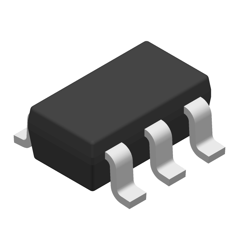
3D Model
Available Download Formats
By downloading CAD models, you agree to our Terms & Conditions and Privacy Policy

Synchronous rectifier controller With Ultra-Low Standby current 6-SOT-23 -40 to 125
Tip: Data for a part may vary between manufacturers. You can filter for manufacturers on the top of the page next to the part image and part number.
UCC24636DBVT by Texas Instruments is an Other Signal Circuit.
Other Signal Circuits are under the broader part category of Signal Circuits.
A signal is an electronic means of transmitting information, either as an analog signal with continuous values or a digital signal with discrete values. Signals are used in various systems and networks. Read more about Signal Circuits on our Signal Circuits part category page.
| Part # | Distributor | Description | Stock | Price | Buy | |
|---|---|---|---|---|---|---|
|
DISTI #
296-44044-1-ND
|
DigiKey | IC REG SR CTRLR SYNC SOT23-6 Min Qty: 1 Lead time: 12 Weeks Container: Digi-Reel®, Cut Tape (CT), Tape & Reel (TR) |
209 In Stock |
|
$0.6201 / $1.3300 | Buy Now |
|
DISTI #
595-UCC24636DBVT
|
Mouser Electronics | Gate Drivers Sync Rectifier Contr oller A 595-UCC24636DBVR RoHS: Compliant | 611 |
|
$0.6020 / $1.3300 | Buy Now |
|
DISTI #
V72:2272_14839621
|
Arrow Electronics | AC to DC Switching Converter Flyback 130kHz T/R 6-Pin SOT-23 RoHS: Compliant Min Qty: 1 Package Multiple: 1 Lead time: 12 Weeks Date Code: 1614 Container: Cut Strips | Americas - 7 |
|
$0.5471 | Buy Now |
|
|
Win Source Electronics | IC REG SR CTRLR SYNC SOT23-6 | 14180 |
|
$0.9625 / $1.2432 | Buy Now |
By downloading CAD models, you agree to our Terms & Conditions and Privacy Policy
|
|
UCC24636DBVT
Texas Instruments
Buy Now
Datasheet
|
Compare Parts:
UCC24636DBVT
Texas Instruments
Synchronous rectifier controller With Ultra-Low Standby current 6-SOT-23 -40 to 125
|
| Pbfree Code | Yes | |
| Rohs Code | Yes | |
| Part Life Cycle Code | Active | |
| Ihs Manufacturer | TEXAS INSTRUMENTS INC | |
| Reach Compliance Code | compliant | |
| ECCN Code | EAR99 | |
| HTS Code | 8542.39.00.01 | |
| Date Of Intro | 2016-03-15 | |
| Samacsys Manufacturer | Texas Instruments | |
| Additional Feature | ALSO OPERATES IN ADJUSTABLE MODE FROM 5 TO 24V | |
| Analog IC - Other Type | ANALOG CIRCUIT | |
| Input Voltage-Max | 28 V | |
| Input Voltage-Min | 3.75 V | |
| Input Voltage-Nom | 12 V | |
| JESD-30 Code | R-PDSO-G6 | |
| JESD-609 Code | e4 | |
| Length | 2.9 mm | |
| Moisture Sensitivity Level | 1 | |
| Number of Channels | 1 | |
| Number of Functions | 1 | |
| Number of Terminals | 6 | |
| Operating Temperature-Max | 125 °C | |
| Operating Temperature-Min | -40 °C | |
| Package Body Material | PLASTIC/EPOXY | |
| Package Code | LSSOP | |
| Package Shape | RECTANGULAR | |
| Package Style | SMALL OUTLINE, LOW PROFILE, SHRINK PITCH | |
| Peak Reflow Temperature (Cel) | 260 | |
| Seated Height-Max | 1.45 mm | |
| Supply Voltage-Max (Vsup) | 28 V | |
| Supply Voltage-Min (Vsup) | 3.75 V | |
| Supply Voltage-Nom (Vsup) | 12 V | |
| Surface Mount | YES | |
| Switcher Configuration | SINGLE | |
| Switching Frequency-Max | 130 kHz | |
| Temperature Grade | AUTOMOTIVE | |
| Terminal Finish | Nickel/Palladium/Gold (Ni/Pd/Au) | |
| Terminal Form | GULL WING | |
| Terminal Pitch | 0.95 mm | |
| Terminal Position | DUAL | |
| Time@Peak Reflow Temperature-Max (s) | 30 | |
| Width | 1.6 mm |
For optimal thermal performance, it is recommended to have a solid ground plane on the bottom layer of the PCB, and to use thermal vias to connect the exposed pad to the ground plane. Additionally, keeping the component placement and routing symmetrical can help reduce thermal gradients.
To ensure reliable operation across the entire operating temperature range, it is essential to follow the recommended operating conditions, including voltage and current ratings. Additionally, consider using thermal management techniques, such as heat sinks or thermal interfaces, to maintain a safe junction temperature.
For EMI filtering and noise reduction, consider using a pi-filter configuration with a common-mode choke and capacitors. Additionally, ensure that the layout is designed to minimize loop areas and that the device is placed close to the power source to reduce noise coupling.
To optimize the design for low power consumption, consider using a low-dropout regulator (LDO) or a switching regulator with a high power conversion efficiency. Additionally, minimize the quiescent current by selecting components with low standby current and using power gating techniques.
Critical parameters to monitor for fault detection and protection include input voltage, output voltage, output current, and temperature. Implementing overvoltage protection, undervoltage protection, and overcurrent protection can help prevent damage to the device and ensure reliable operation.