-
Part Symbol
-
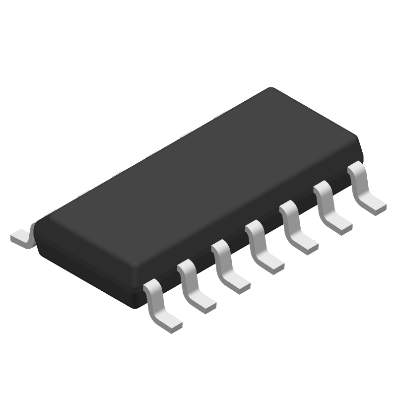
Footprint
-
3D Model
Available Download Formats
By downloading CAD models, you agree to our Terms & Conditions and Privacy Policy

8-Bit, 10 us Quad DAC, Serial Input, Pgrmable for 1x or 2x Output, Simultaneous Update, Low Power 14-SOIC -40 to 85
Tip: Data for a part may vary between manufacturers. You can filter for manufacturers on the top of the page next to the part image and part number.
TLC5620IDRG4 by Texas Instruments is a Digital to Analog Converter.
Digital to Analog Converters are under the broader part category of Converters.
A converter is an electrical circuit that transforms electric energy into a different form that will support a elecrical load needed by a device. Read more about Converters on our Converters part category page.
| Part # | Distributor | Description | Stock | Price | Buy | |
|---|---|---|---|---|---|---|
|
DISTI #
595-TLC5620IDRG4
|
Mouser Electronics | Digital to Analog Converters - DAC 8-Bit 10us Quad DAC Serial Input ALT 595-TLC5620IDR RoHS: Compliant | 0 |
|
$3.3200 | Order Now |
|
|
Vyrian | Converters | 1384 |
|
RFQ | |
|
|
Win Source Electronics | QUADRUPLE 8-BIT DIGITAL-TO-ANALOG CONVERTERS | IC DAC 8BIT V-OUT 14SOIC | 2360 |
|
$3.7538 / $5.6306 | Buy Now |
By downloading CAD models, you agree to our Terms & Conditions and Privacy Policy
|
|
TLC5620IDRG4
Texas Instruments
Buy Now
Datasheet
|
Compare Parts:
TLC5620IDRG4
Texas Instruments
8-Bit, 10 us Quad DAC, Serial Input, Pgrmable for 1x or 2x Output, Simultaneous Update, Low Power 14-SOIC -40 to 85
|
| Pbfree Code | Yes | |
| Rohs Code | Yes | |
| Part Life Cycle Code | Active | |
| Ihs Manufacturer | TEXAS INSTRUMENTS INC | |
| Part Package Code | SOIC | |
| Package Description | SOP, SOP14,.25 | |
| Pin Count | 14 | |
| Reach Compliance Code | compliant | |
| HTS Code | 8542.39.00.01 | |
| Samacsys Manufacturer | Texas Instruments | |
| Analog Output Voltage-Max | 7 V | |
| Analog Output Voltage-Min | ||
| Converter Type | D/A CONVERTER | |
| Input Bit Code | BINARY | |
| Input Format | SERIAL | |
| JESD-30 Code | R-PDSO-G14 | |
| JESD-609 Code | e4 | |
| Length | 8.65 mm | |
| Linearity Error-Max (EL) | 0.3906% | |
| Moisture Sensitivity Level | 1 | |
| Number of Bits | 8 | |
| Number of Functions | 1 | |
| Number of Terminals | 14 | |
| Operating Temperature-Max | 85 °C | |
| Operating Temperature-Min | -40 °C | |
| Package Body Material | PLASTIC/EPOXY | |
| Package Code | SOP | |
| Package Equivalence Code | SOP14,.25 | |
| Package Shape | RECTANGULAR | |
| Package Style | SMALL OUTLINE | |
| Peak Reflow Temperature (Cel) | 260 | |
| Qualification Status | Not Qualified | |
| Sample Rate | 0.048 MHz | |
| Seated Height-Max | 1.75 mm | |
| Settling Time-Max | 10 µs | |
| Settling Time-Nom (tstl) | 10 µs | |
| Supply Current-Max | 2 mA | |
| Supply Voltage-Nom | 5 V | |
| Surface Mount | YES | |
| Technology | CMOS | |
| Temperature Grade | INDUSTRIAL | |
| Terminal Finish | Nickel/Palladium/Gold (Ni/Pd/Au) | |
| Terminal Form | GULL WING | |
| Terminal Pitch | 1.27 mm | |
| Terminal Position | DUAL | |
| Time@Peak Reflow Temperature-Max (s) | 30 | |
| Width | 3.905 mm |
The recommended power-on sequence is to apply VCC first, followed by VREF, and then the digital inputs. This ensures proper device operation and prevents latch-up.
To ensure accurate DAC output voltage levels, it's essential to use a low-impedance voltage reference (VREF) and to decouple the VREF pin with a capacitor to reduce noise. Additionally, use a high-precision resistor network for the output stage.
The maximum clock frequency for the TLC5620 is 40 MHz. However, the actual clock frequency may be limited by the specific application and the quality of the clock signal.
The power-down mode (PD) pin should be tied to a logic high (VCC) or left floating to enable normal device operation. Tying the PD pin to a logic low (GND) will put the device into power-down mode, reducing power consumption.
The CLR (clear) pin is used to asynchronously clear the DAC output to zero. This pin can be used to reset the DAC output to zero during power-up or when the device is in power-down mode.