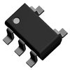
Part Details for TK11125CSCL-G by TOKO Inc
Results Overview of TK11125CSCL-G by TOKO Inc
- Distributor Offerings: (0 listings)
- Number of FFF Equivalents: (1 replacement)
- CAD Models: (Request Part)
- Number of Functional Equivalents: (1 option)
- Part Data Attributes: (Available)
- Reference Designs: (Not Available)
Tip: Data for a part may vary between manufacturers. You can filter for manufacturers on the top of the page next to the part image and part number.
TK11125CSCL-G Information
TK11125CSCL-G by TOKO Inc is a Linear Regulator IC.
Linear Regulator ICs are under the broader part category of Power Circuits.
A power circuit delivers electricity in order to operate a load for an electronic device. Power circuits include transformers, generators and switches. Read more about Power Circuits on our Power Circuits part category page.
Part Details for TK11125CSCL-G
TK11125CSCL-G CAD Models
TK11125CSCL-G Part Data Attributes
|
|
TK11125CSCL-G
TOKO Inc
Buy Now
Datasheet
|
Compare Parts:
TK11125CSCL-G
TOKO Inc
Fixed Positive LDO Regulator, 2.5V, 0.14V Dropout, PDSO5, LEAD FREE, SOT-23, 5 PIN
|
| Pbfree Code | Yes | |
| Part Life Cycle Code | Obsolete | |
| Ihs Manufacturer | TOKO INC | |
| Part Package Code | SOT-23 | |
| Package Description | LEAD FREE, SOT-23, 5 PIN | |
| Pin Count | 5 | |
| Reach Compliance Code | unknown | |
| ECCN Code | EAR99 | |
| HTS Code | 8542.39.00.01 | |
| Dropout Voltage1-Max | 0.14 V | |
| JESD-30 Code | R-PDSO-G5 | |
| Number of Functions | 1 | |
| Number of Terminals | 5 | |
| Output Current1-Max | 0.24 A | |
| Output Voltage1-Max | 2.5375 V | |
| Output Voltage1-Min | 2.4625 V | |
| Package Body Material | PLASTIC/EPOXY | |
| Package Code | SOP | |
| Package Shape | RECTANGULAR | |
| Package Style | SMALL OUTLINE | |
| Regulator Type | FIXED POSITIVE SINGLE OUTPUT LDO REGULATOR | |
| Surface Mount | YES | |
| Terminal Form | GULL WING | |
| Terminal Position | DUAL |
Alternate Parts for TK11125CSCL-G
This table gives cross-reference parts and alternative options found for TK11125CSCL-G. The Form Fit Function (FFF) tab will give you the options that are more likely to serve as direct pin-to-pin alternates or drop-in parts. The Functional Equivalents tab will give you options that are likely to match the same function of TK11125CSCL-G, but it may not fit your design. Always verify details of parts you are evaluating, as these parts are offered as suggestions for what you are looking for and are not guaranteed.
| Part Number | Manufacturer | Composite Price | Description | Compare |
|---|---|---|---|---|
| TK11125CSCL-GH | Asahi Kasei Microsystems Corporation | Check for Price | Fixed Positive LDO Regulator, | TK11125CSCL-G vs TK11125CSCL-GH |
TK11125CSCL-G Frequently Asked Questions (FAQ)
-
TOKO recommends a PCB layout with a symmetrical and balanced design to minimize electromagnetic interference. A land pattern with a 1.5mm to 2.0mm pad size and a 0.5mm to 1.0mm gap between pads is recommended. Additionally, a ground plane underneath the inductor can help reduce radiation.
-
While the datasheet only specifies up to 100 MHz, the TK11125CSCL-G can be used in high-frequency applications up to 500 MHz with some degradation in performance. However, it's essential to consult with TOKO's application engineers to determine the suitability of the inductor for specific high-frequency applications.
-
The maximum allowable current for the TK11125CSCL-G in saturation mode is approximately 1.5 to 2 times the rated current. However, this value can vary depending on the specific application and operating conditions. It's recommended to consult with TOKO's application engineers to determine the safe operating area for the inductor.
-
While the datasheet specifies an operating temperature range of -40°C to 125°C, the TK11125CSCL-G can be used in high-temperature environments up to 150°C with some derating. However, it's essential to consult with TOKO's application engineers to determine the suitable operating temperature range for specific applications.
-
TOKO recommends storing the TK11125CSCL-G in a dry, cool place away from direct sunlight and moisture. The inductor should be handled with care to prevent mechanical stress, and electrostatic discharge (ESD) precautions should be taken to prevent damage to the component.
