-
Part Symbol
-
Footprint
-
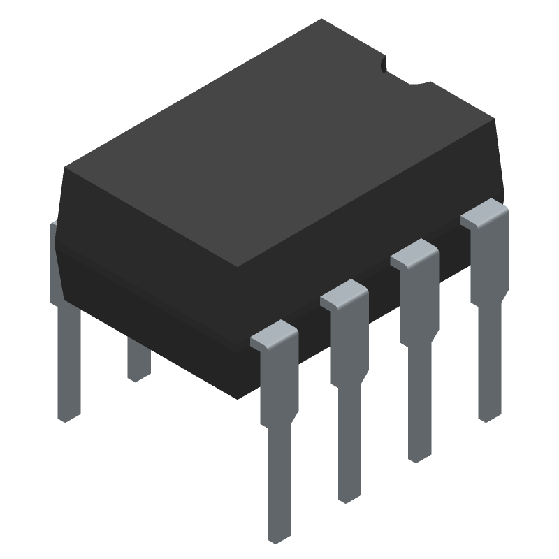
3D Model
Available Download Formats
By downloading CAD models, you agree to our Terms & Conditions and Privacy Policy
8-Pin DIP AC Line Monitor Logic Output Optocoupler, PDIP-8, 1000-TUBE
Tip: Data for a part may vary between manufacturers. You can filter for manufacturers on the top of the page next to the part image and part number.
MID400 by onsemi is an Optocoupler.
Optocoupler are under the broader part category of Optoelectronics.
Optoelectronic components work to detect, generate, and control light. They can essentially produce and/or react to light. Read more about Optoelectronics on our Optoelectronics part category page.
| Part # | Distributor | Description | Stock | Price | Buy | |
|---|---|---|---|---|---|---|
|
DISTI #
63K5677
|
Newark | Optocoupler, Transistor, 2500Vrms, No. Of Channels:1 Channel, Optocoupler Case Style:Dip, No. Of Pins:8Pins, Forward Current If Max:-, Isolation Voltage:2.5Kv, Ctr Min:-, Collector Emitter Voltage V(Br)Ceo:7V, Product Range:- Rohs Compliant: Yes |Onsemi MID400 RoHS: Compliant Min Qty: 1000 Package Multiple: 1 Date Code: 0 Container: Bulk | 0 |
|
Buy Now |
By downloading CAD models, you agree to our Terms & Conditions and Privacy Policy
|
|
MID400
onsemi
Buy Now
Datasheet
|
Compare Parts:
MID400
onsemi
8-Pin DIP AC Line Monitor Logic Output Optocoupler, PDIP-8, 1000-TUBE
|
| Pbfree Code | Yes | |
| Rohs Code | Yes | |
| Part Life Cycle Code | Obsolete | |
| Ihs Manufacturer | ONSEMI | |
| Part Package Code | PDIP-8 | |
| Package Description | DIP-8 | |
| Manufacturer Package Code | 646CQ | |
| Reach Compliance Code | compliant | |
| HTS Code | 8541.40.80.00 | |
| Samacsys Manufacturer | onsemi | |
| Additional Feature | UL RECOGNIZED, TTL COMPATIBLE | |
| Configuration | SINGLE | |
| Forward Current-Max | 0.03 A | |
| Isolation Voltage-Max | 2500 V | |
| JESD-609 Code | e3 | |
| Mounting Feature | THROUGH HOLE MOUNT | |
| Number of Elements | 1 | |
| Number of Functions | 1 | |
| Operating Temperature-Max | 85 °C | |
| Operating Temperature-Min | -40 °C | |
| Optoelectronic Device Type | LOGIC IC OUTPUT OPTOCOUPLER | |
| Power Dissipation-Max | 0.07 W | |
| Response Time-Nom | 0.001 ns | |
| Supply Voltage-Nom | 5 V | |
| Surface Mount | NO | |
| Terminal Finish | Matte Tin (Sn) - annealed |
This table gives cross-reference parts and alternative options found for MID400. The Form Fit Function (FFF) tab will give you the options that are more likely to serve as direct pin-to-pin alternates or drop-in parts. The Functional Equivalents tab will give you options that are likely to match the same function of MID400, but it may not fit your design. Always verify details of parts you are evaluating, as these parts are offered as suggestions for what you are looking for and are not guaranteed.
| Part Number | Manufacturer | Composite Price | Description | Compare |
|---|---|---|---|---|
| MID400 | Quality Technologies Corp | Check for Price | Logic IC Output Optocoupler, | MID400 vs MID400 |
| MID400V | Fairchild Semiconductor Corporation | Check for Price | Logic IC Output Optocoupler, 1-Element, 2500V Isolation, PLASTIC, DIP-8 | MID400 vs MID400V |
A good PCB layout for the MID400 involves keeping the input and output stages separate, using a star-ground configuration, and minimizing the length of the input and output traces. A 4-layer PCB with a solid ground plane is recommended.
The MID400 requires a bias voltage of 5V to 15V, and the recommended bias current is 10mA to 20mA. A voltage regulator or a zener diode can be used to generate the bias voltage. Ensure the bias voltage is stable and noise-free for optimal performance.
The MID400 can handle up to 400W of power, but this depends on the specific application and the thermal management of the device. Ensure proper heat sinking and thermal management to prevent overheating and damage to the device.
Use a voltage regulator or a voltage limiter to prevent overvoltage conditions. For overcurrent protection, use a current limiter or a fuse in series with the MID400. Additionally, ensure the device is properly heat-sinked to prevent thermal runaway.
The MID400 is designed to operate from DC to 500 kHz, but the optimal frequency range depends on the specific application. For most applications, an operating frequency range of 100 kHz to 200 kHz is recommended.