-
Part Symbol
-
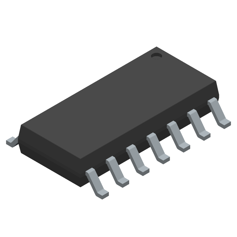
Footprint
-
3D Model
Available Download Formats
By downloading CAD models, you agree to our Terms & Conditions and Privacy Policy
+3.3V, ±15kV ESD-Protected, Fail-Safe, Hot-Swap, RS-485/RS-422 Transceivers, 14-SOIC_N-150_MIL, 14 Pins, -40 to 85C
Tip: Data for a part may vary between manufacturers. You can filter for manufacturers on the top of the page next to the part image and part number.
MAX3070EESD+T by Analog Devices Inc is a Line Driver or Receiver.
Line Driver or Receivers are under the broader part category of Drivers And Interfaces.
A driver controls the current or voltage delivered to components like LCDs or motors, while an interface component connects systems for data transfer and control. Read more about Drivers And Interfaces on our Drivers And Interfaces part category page.
| Part # | Distributor | Description | Stock | Price | Buy | |
|---|---|---|---|---|---|---|
|
DISTI #
73Y3146
|
Newark | Rs422/Rs485 Txrx, 250Kbps, 3.63V, Nsoic, Ic Type:Rs422/Rs485 Transceiver, No. Of Receivers:1Receivers, No. Of Transmitters:1, Communication Mode:Full Duplex, Data Rate Max:250Kbps, Supply Voltage Min:2.97V, Supply Voltage Max:3.63Vrohs Compliant: Yes |Analog Devices MAX3070EESD+T RoHS: Compliant Min Qty: 1 Package Multiple: 1 Date Code: 1 Container: Cut Tape | 631 |
|
$4.8000 / $8.4700 | Buy Now |
|
DISTI #
700-MAX3070EESDT
|
Mouser Electronics | RS-422/RS-485 Interface IC +3.3V, 15kV ESD-Protected, Fail-Safe, Hot-Swap, RS-485/RS-422 Transceivers RoHS: Compliant | 5473 |
|
$4.7400 / $8.4700 | Buy Now |
|
|
Analog Devices Inc | +3.3V, ±15kV ESD-Protected, Fa Min Qty: 1 Package Multiple: 1 | 647 |
|
$4.9202 / $8.4700 | Buy Now |
By downloading CAD models, you agree to our Terms & Conditions and Privacy Policy
|
|
MAX3070EESD+T
Analog Devices Inc
Buy Now
Datasheet
|
Compare Parts:
MAX3070EESD+T
Analog Devices Inc
+3.3V, ±15kV ESD-Protected, Fail-Safe, Hot-Swap, RS-485/RS-422 Transceivers, 14-SOIC_N-150_MIL, 14 Pins, -40 to 85C
|
| Rohs Code | Yes | |
| Part Life Cycle Code | Active | |
| Ihs Manufacturer | ANALOG DEVICES INC | |
| Part Package Code | 14-SOIC_N-150_MIL | |
| Package Description | 0.150 INCH, MS-012AB, SOIC-14 | |
| Pin Count | 14 | |
| Manufacturer Package Code | 14-SOIC_N-150_MIL | |
| Reach Compliance Code | compliant | |
| Date Of Intro | 2002-11-22 | |
| Samacsys Manufacturer | Analog Devices | |
| Differential Output | YES | |
| Driver Number of Bits | 1 | |
| Input Characteristics | DIFFERENTIAL SCHMITT TRIGGER | |
| Interface IC Type | LINE TRANSCEIVER | |
| Interface Standard | EIA-422; EIA-485; TIA-485 | |
| JESD-30 Code | R-PDSO-G14 | |
| JESD-609 Code | e3 | |
| Length | 8.65 mm | |
| Moisture Sensitivity Level | 1 | |
| Number of Functions | 1 | |
| Number of Terminals | 14 | |
| Operating Temperature-Max | 85 °C | |
| Operating Temperature-Min | -40 °C | |
| Out Swing-Min | 1.5 V | |
| Output Low Current-Max | 0.001 A | |
| Package Body Material | PLASTIC/EPOXY | |
| Package Code | SOP | |
| Package Equivalence Code | SOP14,.25 | |
| Package Shape | RECTANGULAR | |
| Package Style | SMALL OUTLINE | |
| Peak Reflow Temperature (Cel) | 260 | |
| Qualification Status | Not Qualified | |
| Receive Delay-Max | 200 ns | |
| Receiver Number of Bits | 1 | |
| Seated Height-Max | 1.75 mm | |
| Supply Current-Max | 1.5 mA | |
| Supply Voltage-Max | 3.63 V | |
| Supply Voltage-Min | 2.97 V | |
| Supply Voltage-Nom | 3.3 V | |
| Surface Mount | YES | |
| Technology | BICMOS | |
| Temperature Grade | INDUSTRIAL | |
| Terminal Finish | Matte Tin (Sn) | |
| Terminal Form | GULL WING | |
| Terminal Pitch | 1.27 mm | |
| Terminal Position | DUAL | |
| Time@Peak Reflow Temperature-Max (s) | 30 | |
| Transmit Delay-Max | 1500 ns | |
| Width | 3.9 mm |
This table gives cross-reference parts and alternative options found for MAX3070EESD+T. The Form Fit Function (FFF) tab will give you the options that are more likely to serve as direct pin-to-pin alternates or drop-in parts. The Functional Equivalents tab will give you options that are likely to match the same function of MAX3070EESD+T, but it may not fit your design. Always verify details of parts you are evaluating, as these parts are offered as suggestions for what you are looking for and are not guaranteed.
| Part Number | Manufacturer | Composite Price | Description | Compare |
|---|---|---|---|---|
| MAX3070EESD+T | Maxim Integrated Products | Check for Price | Line Transceiver, 1 Func, 1 Driver, 1 Rcvr, BICMOS, PDSO14, 0.150 INCH, MS-012AB, SOIC-14 | MAX3070EESD+T vs MAX3070EESD+T |
| MAX3073EESD | Maxim Integrated Products | Check for Price | Line Transceiver, 1 Func, 1 Driver, 1 Rcvr, BICMOS, PDSO14, 0.150 INCH, MS-012AB, SOIC-14 | MAX3070EESD+T vs MAX3073EESD |
A good PCB layout for the MAX3070EESD+T involves keeping the signal traces short and away from noise sources, using a solid ground plane, and placing bypass capacitors close to the device. Additionally, it's recommended to use a shielded cable for the RS-485 bus and to keep the cable length as short as possible.
Proper termination of the RS-485 bus is crucial for reliable communication. The MAX3070EESD+T requires a termination resistor (typically 120Ω) at each end of the bus, and the bus should be terminated at both the driver and receiver ends. Additionally, the termination resistors should be placed as close to the device as possible.
The maximum cable length supported by the MAX3070EESD+T depends on the data rate and the type of cable used. As a general rule, the maximum cable length is approximately 4000 feet (1219 meters) at a data rate of 10 Mbps, and 1000 feet (305 meters) at a data rate of 35 Mbps. However, it's recommended to consult the datasheet and perform signal integrity analysis to determine the maximum cable length for a specific application.
The MAX3070EESD+T has built-in ESD protection, but additional protection measures can be taken to ensure reliability. These include using ESD protection devices such as TVS diodes, using a shielded enclosure, and following proper handling and storage procedures to prevent ESD damage.
The recommended power-up sequence for the MAX3070EESD+T is to power up the VCC supply first, followed by the VDD supply. This ensures that the internal voltage regulators are properly initialized and that the device operates reliably.