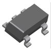
Part Details for LTC6101HVBHS5#TRMPBF by Linear Technology
Results Overview of LTC6101HVBHS5#TRMPBF by Linear Technology
- Distributor Offerings: (2 listings)
- Number of FFF Equivalents: (0 replacements)
- CAD Models: (Request Part)
- Number of Functional Equivalents: (0 options)
- Part Data Attributes: (Available)
- Reference Designs: (Not Available)
Tip: Data for a part may vary between manufacturers. You can filter for manufacturers on the top of the page next to the part image and part number.
LTC6101HVBHS5#TRMPBF Information
LTC6101HVBHS5#TRMPBF by Linear Technology is an Operational Amplifier.
Operational Amplifiers are under the broader part category of Amplifier Circuits.
Amplifier circuits use external power to increase the amplitude of an input signal. They can be used to perform linear amplifications or logarithmic functions. Read more about Amplifier Circuits on our Amplifier Circuits part category page.
Price & Stock for LTC6101HVBHS5#TRMPBF
| Part # | Distributor | Description | Stock | Price | Buy | |
|---|---|---|---|---|---|---|
|
|
Bristol Electronics | 500 |
|
RFQ | ||
|
|
Vyrian | Amplifiers | 553 |
|
RFQ |
Part Details for LTC6101HVBHS5#TRMPBF
LTC6101HVBHS5#TRMPBF CAD Models
LTC6101HVBHS5#TRMPBF Part Data Attributes
|
|
LTC6101HVBHS5#TRMPBF
Linear Technology
Buy Now
Datasheet
|
Compare Parts:
LTC6101HVBHS5#TRMPBF
Linear Technology
LTC6101 - High Voltage, High-Side Current Sense Amplifier in SOT-23; Package: SOT; Pins: 5; Temperature Range: -40°C to 125°C
|
| Rohs Code | Yes | |
| Part Life Cycle Code | Transferred | |
| Ihs Manufacturer | LINEAR TECHNOLOGY CORP | |
| Part Package Code | SOT | |
| Package Description | TSOT-23, 5 PIN | |
| Pin Count | 5 | |
| Manufacturer Package Code | S5 | |
| Reach Compliance Code | compliant | |
| ECCN Code | EAR99 | |
| HTS Code | 8542.33.00.01 | |
| Amplifier Type | OPERATIONAL AMPLIFIER | |
| Architecture | VOLTAGE-FEEDBACK | |
| Average Bias Current-Max (IIB) | 0.245 µA | |
| Bias Current-Max (IIB) @25C | 0.17 µA | |
| Frequency Compensation | YES | |
| Input Offset Voltage-Max | 810 µV | |
| JESD-30 Code | R-PDSO-G5 | |
| Length | 2.9 mm | |
| Low-Bias | NO | |
| Low-Offset | YES | |
| Micropower | NO | |
| Number of Functions | 1 | |
| Number of Terminals | 5 | |
| Operating Temperature-Max | 125 °C | |
| Operating Temperature-Min | -40 °C | |
| Package Body Material | PLASTIC/EPOXY | |
| Package Code | LSSOP | |
| Package Equivalence Code | TSOP5/6,.11,37 | |
| Package Shape | RECTANGULAR | |
| Package Style | SMALL OUTLINE, LOW PROFILE, SHRINK PITCH | |
| Packing Method | TR | |
| Power | NO | |
| Programmable Power | NO | |
| Seated Height-Max | 1 mm | |
| Supply Current-Max | 0.72 mA | |
| Supply Voltage Limit-Max | 105 V | |
| Supply Voltage-Nom (Vsup) | 6 V | |
| Surface Mount | YES | |
| Technology | CMOS | |
| Terminal Form | GULL WING | |
| Terminal Pitch | 0.95 mm | |
| Terminal Position | DUAL | |
| Wideband | NO | |
| Width | 1.625 mm |
LTC6101HVBHS5#TRMPBF Frequently Asked Questions (FAQ)
-
The maximum power dissipation of the LTC6101HVBHS5 is dependent on the thermal resistance of the package and the ambient temperature. According to the datasheet, the maximum power dissipation is approximately 1.4W at 25°C ambient temperature.
-
To optimize the layout for the LTC6101HVBHS5, it is recommended to follow the guidelines provided in the datasheet, including keeping the input and output capacitors close to the device, using a solid ground plane, and minimizing the length of the input and output traces.
-
The recommended input capacitor value for the LTC6101HVBHS5 is 10uF to 22uF, with a voltage rating of at least 50V. The capacitor should be placed as close to the VIN pin as possible.
-
The LTC6101HVBHS5 is rated for operation from -40°C to 125°C. However, the device's performance and reliability may be affected at high temperatures. It is recommended to consult the datasheet and application notes for guidance on using the device in high-temperature environments.
-
To protect the LTC6101HVBHS5 from overvoltage and overcurrent, it is recommended to use a voltage regulator with overvoltage protection (OVP) and overcurrent protection (OCP) features. Additionally, a fuse or a current-limiting resistor can be used to prevent excessive current from flowing into the device.
