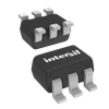
Part Details for ISL3283EFHZ-T7A by Intersil Corporation
Results Overview of ISL3283EFHZ-T7A by Intersil Corporation
- Distributor Offerings: (0 listings)
- Number of FFF Equivalents: (0 replacements)
- CAD Models: (Request Part)
- Number of Functional Equivalents: (0 options)
- Part Data Attributes: (Available)
- Reference Designs: (Not Available)
Tip: Data for a part may vary between manufacturers. You can filter for manufacturers on the top of the page next to the part image and part number.
ISL3283EFHZ-T7A Information
ISL3283EFHZ-T7A by Intersil Corporation is a Line Driver or Receiver.
Line Driver or Receivers are under the broader part category of Drivers And Interfaces.
A driver controls the current or voltage delivered to components like LCDs or motors, while an interface component connects systems for data transfer and control. Read more about Drivers And Interfaces on our Drivers And Interfaces part category page.
Part Details for ISL3283EFHZ-T7A
ISL3283EFHZ-T7A CAD Models
ISL3283EFHZ-T7A Part Data Attributes
|
|
ISL3283EFHZ-T7A
Intersil Corporation
Buy Now
Datasheet
|
Compare Parts:
ISL3283EFHZ-T7A
Intersil Corporation
±16.5kV ESD Protected, SOT-23, 20Mbps, with active low Rx enable, RS-485/RS-422 Receiver; SOT6; Temp Range: See Datasheet
|
| Rohs Code | Yes | |
| Part Life Cycle Code | Transferred | |
| Ihs Manufacturer | INTERSIL CORP | |
| Part Package Code | SOT | |
| Package Description | ROHS COMPLIANT, PLASTIC, MO-178AB, SOT-23, 6 PIN | |
| Pin Count | 6 | |
| Reach Compliance Code | compliant | |
| ECCN Code | EAR99 | |
| HTS Code | 8542.39.00.01 | |
| Factory Lead Time | 26 Weeks | |
| Input Characteristics | DIFFERENTIAL SCHMITT TRIGGER | |
| Interface IC Type | LINE RECEIVER | |
| Interface Standard | EIA-485; EIA-422 | |
| JESD-30 Code | R-PDSO-G6 | |
| JESD-609 Code | e3 | |
| Length | 2.9 mm | |
| Moisture Sensitivity Level | 2 | |
| Number of Functions | 1 | |
| Number of Terminals | 6 | |
| Operating Temperature-Max | 125 °C | |
| Operating Temperature-Min | -40 °C | |
| Package Body Material | PLASTIC/EPOXY | |
| Package Code | LSSOP | |
| Package Shape | RECTANGULAR | |
| Package Style | SMALL OUTLINE, LOW PROFILE, SHRINK PITCH | |
| Peak Reflow Temperature (Cel) | 260 | |
| Receive Delay-Max | 60 ns | |
| Receiver Number of Bits | 1 | |
| Seated Height-Max | 1.45 mm | |
| Supply Voltage-Max | 5.5 V | |
| Supply Voltage-Min | 3 V | |
| Supply Voltage-Nom | 3.3 V | |
| Surface Mount | YES | |
| Technology | BICMOS | |
| Temperature Grade | AUTOMOTIVE | |
| Terminal Finish | MATTE TIN | |
| Terminal Form | GULL WING | |
| Terminal Pitch | 0.95 mm | |
| Terminal Position | DUAL | |
| Time@Peak Reflow Temperature-Max (s) | 30 | |
| Width | 1.6 mm |
ISL3283EFHZ-T7A Frequently Asked Questions (FAQ)
-
The recommended PCB layout for the ISL3283EFHZ-T7A involves placing the device close to the signal source, using short traces, and minimizing the number of vias. Additionally, a solid ground plane and a separate power plane are recommended to reduce noise and electromagnetic interference (EMI).
-
The ISL3283EFHZ-T7A has a maximum junction temperature of 150°C. To handle thermal management, ensure good airflow around the device, use a heat sink if necessary, and avoid blocking the airflow around the device. Also, ensure that the PCB is designed to dissipate heat efficiently.
-
The recommended input signal amplitude for the ISL3283EFHZ-T7A is between 100mV and 1.4V, and the frequency range is from DC to 100MHz. However, the specific input signal requirements may vary depending on the application, so it's essential to consult the datasheet and application notes for more information.
-
To ensure the ISL3283EFHZ-T7A is properly biased and configured, consult the datasheet and application notes for specific guidelines on biasing and configuration. Additionally, consider consulting with an experienced engineer or seeking support from the manufacturer or a third-party expert if you're unsure about the biasing and configuration requirements for your application.
-
Common failure modes of the ISL3283EFHZ-T7A include overheating, overvoltage, and electrostatic discharge (ESD). To mitigate these failure modes, ensure proper thermal management, use voltage regulators and protection circuits to prevent overvoltage, and follow proper handling and storage procedures to prevent ESD damage.
