-
Part Symbol
-
Footprint
-
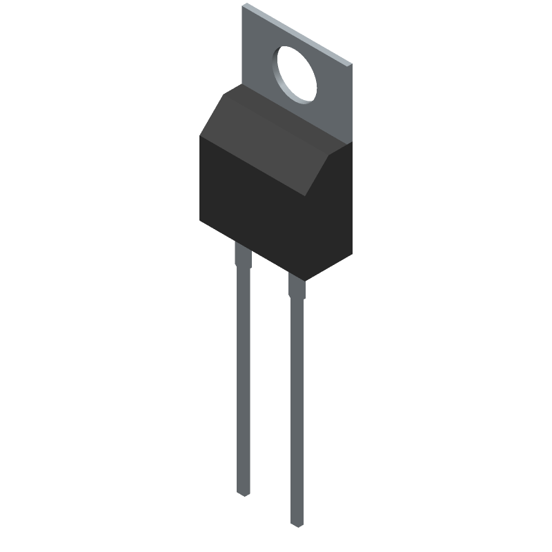
3D Model
Available Download Formats
By downloading CAD models, you agree to our Terms & Conditions and Privacy Policy
Rectifier Diode,
Tip: Data for a part may vary between manufacturers. You can filter for manufacturers on the top of the page next to the part image and part number.
IDP40E65D2 by Infineon Technologies AG is a Rectifier Diode.
Rectifier Diodes are under the broader part category of Diodes.
A diode is a electrical part that can control the direction in which the current flows in a device. Consider factors like voltage drop, current capacity, reverse voltage, and operating frequency when selecting a diode. Read more about Diodes on our Diodes part category page.
| Part # | Distributor | Description | Stock | Price | Buy | |
|---|---|---|---|---|---|---|
|
DISTI #
726-IDP40E65D2
|
Mouser Electronics | Small Signal Switching Diodes IGBT PRODUCTS Rapid Switching RoHS: Compliant | 243 |
|
$0.8100 / $2.1300 | Buy Now |
By downloading CAD models, you agree to our Terms & Conditions and Privacy Policy
|
|
IDP40E65D2
Infineon Technologies AG
Buy Now
Datasheet
|
Compare Parts:
IDP40E65D2
Infineon Technologies AG
Rectifier Diode,
|
| Pbfree Code | Yes | |
| Rohs Code | Yes | |
| Part Life Cycle Code | Active | |
| Ihs Manufacturer | INFINEON TECHNOLOGIES AG | |
| Package Description | TO-220, 2 PIN | |
| Reach Compliance Code | compliant | |
| ECCN Code | EAR99 | |
| HTS Code | 8541.10.00.80 | |
| Samacsys Manufacturer | Infineon | |
| Additional Feature | PD-CASE | |
| Application | FAST SOFT RECOVERY | |
| Case Connection | CATHODE | |
| Configuration | SINGLE | |
| Diode Element Material | SILICON | |
| Diode Type | RECTIFIER DIODE | |
| Forward Voltage-Max (VF) | 2.2 V | |
| JEDEC-95 Code | TO-220AC | |
| JESD-30 Code | R-PSFM-T2 | |
| JESD-609 Code | e3 | |
| Non-rep Pk Forward Current-Max | 250 A | |
| Number of Elements | 1 | |
| Number of Phases | 1 | |
| Number of Terminals | 2 | |
| Operating Temperature-Max | 175 °C | |
| Operating Temperature-Min | -40 °C | |
| Output Current-Max | 80 A | |
| Package Body Material | PLASTIC/EPOXY | |
| Package Shape | RECTANGULAR | |
| Package Style | FLANGE MOUNT | |
| Peak Reflow Temperature (Cel) | NOT SPECIFIED | |
| Power Dissipation-Max | 200 W | |
| Rep Pk Reverse Voltage-Max | 650 V | |
| Reverse Current-Max | 40 µA | |
| Reverse Recovery Time-Max | 0.075 µs | |
| Reverse Test Voltage | 650 V | |
| Surface Mount | NO | |
| Terminal Finish | Tin (Sn) | |
| Terminal Form | THROUGH-HOLE | |
| Terminal Position | SINGLE | |
| Time@Peak Reflow Temperature-Max (s) | NOT SPECIFIED |
Infineon provides a recommended PCB layout in their application note AN2019-01, which includes guidelines for thermal vias, copper thickness, and component placement to ensure optimal thermal performance.
Infineon recommends using a gate driver with a high current capability (e.g., 2A to 5A) and a low propagation delay (e.g., <10ns) to ensure proper switching of the IDP40E65D2. The gate driver should also be compatible with the device's gate-source voltage rating.
According to Infineon's application note AN2019-01, the maximum allowed voltage overshoot during turn-on and turn-off is 10% of the maximum drain-source voltage (VDS) rating, which is 650V for the IDP40E65D2.
Implementing overvoltage protection (OVP) and undervoltage protection (UVP) circuits can help ensure safe operation. Infineon recommends using a voltage monitor IC or a dedicated OVP/UVP IC to detect and respond to voltage anomalies.
For high-power applications, Infineon recommends using a heat sink with a thermal interface material (TIM) to improve heat transfer. The heat sink should be designed to provide a low thermal resistance (Rth) and should be attached to the device using a suitable mounting method (e.g., screw or clip).