-
Part Symbol
-
Footprint
-
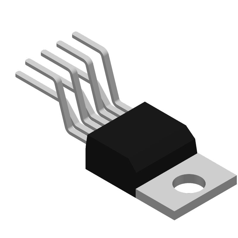
3D Model
Available Download Formats
By downloading CAD models, you agree to our Terms & Conditions and Privacy Policy

PWM Solenoid/Valve Driver 7-TO-220 -40 to 85
Tip: Data for a part may vary between manufacturers. You can filter for manufacturers on the top of the page next to the part image and part number.
DRV101TG3 by Texas Instruments is a Peripheral Driver.
Peripheral Drivers are under the broader part category of Drivers And Interfaces.
A driver controls the current or voltage delivered to components like LCDs or motors, while an interface component connects systems for data transfer and control. Read more about Drivers And Interfaces on our Drivers And Interfaces part category page.
| Part # | Distributor | Description | Stock | Price | Buy | |
|---|---|---|---|---|---|---|
|
|
Vyrian | Peripheral ICs | 703 |
|
RFQ |
By downloading CAD models, you agree to our Terms & Conditions and Privacy Policy
|
|
DRV101TG3
Texas Instruments
Buy Now
Datasheet
|
Compare Parts:
DRV101TG3
Texas Instruments
PWM Solenoid/Valve Driver 7-TO-220 -40 to 85
|
| Rohs Code | Yes | |
| Part Life Cycle Code | Obsolete | |
| Ihs Manufacturer | TEXAS INSTRUMENTS INC | |
| Part Package Code | SFM | |
| Package Description | TO-220, 7 PIN | |
| Pin Count | 3 | |
| Reach Compliance Code | compliant | |
| ECCN Code | EAR99 | |
| HTS Code | 8542.39.00.01 | |
| Samacsys Manufacturer | Texas Instruments | |
| Built-in Protections | OVER CURRENT; THERMAL | |
| Driver Number of Bits | 1 | |
| Interface IC Type | BUFFER OR INVERTER BASED PERIPHERAL DRIVER | |
| JESD-30 Code | R-PZFM-T7 | |
| JESD-609 Code | e3 | |
| Number of Functions | 1 | |
| Number of Terminals | 7 | |
| Operating Temperature-Max | 85 °C | |
| Operating Temperature-Min | -40 °C | |
| Output Current Flow Direction | SINK | |
| Output Current-Max | 1 A | |
| Output Peak Current Limit-Nom | 2.3 A | |
| Package Body Material | PLASTIC/EPOXY | |
| Package Code | ZFM | |
| Package Equivalence Code | ZIP7,.15,.2TB | |
| Package Shape | RECTANGULAR | |
| Package Style | FLANGE MOUNT | |
| Qualification Status | Not Qualified | |
| Supply Voltage-Max | 60 V | |
| Supply Voltage-Min | 9 V | |
| Supply Voltage-Nom | 24 V | |
| Surface Mount | NO | |
| Technology | BIPOLAR | |
| Temperature Grade | INDUSTRIAL | |
| Terminal Finish | MATTE TIN | |
| Terminal Form | THROUGH-HOLE | |
| Terminal Pitch | 1.27 mm | |
| Terminal Position | ZIG-ZAG |
A good PCB layout for the DRV101TG3 involves keeping the high-current paths short and wide, using a solid ground plane, and placing the input and output capacitors close to the device. A 4-layer PCB with a dedicated power plane and a solid ground plane is recommended.
Choose X7R or X5R ceramic capacitors with a voltage rating of at least 2x the input voltage. The capacitance value depends on the input voltage ripple and output voltage ripple requirements. A minimum of 10uF is recommended for the input capacitor and 22uF for the output capacitor.
The maximum ambient temperature for the DRV101TG3 is 85°C. However, the device can operate up to 125°C junction temperature. Ensure proper thermal design and heat sinking to maintain a safe junction temperature.
Yes, the DRV101TG3 is AEC-Q100 qualified and suitable for automotive and high-reliability applications. However, ensure that the device is used within its recommended operating conditions and that the system design meets the required safety and reliability standards.
Start by checking the input voltage, output voltage, and current. Verify that the device is properly soldered and that the PCB layout is correct. Check for overheating, and ensure that the device is not operating in an overcurrent or overvoltage condition. Consult the datasheet and application notes for more troubleshooting guidance.