-
Part Symbol
-
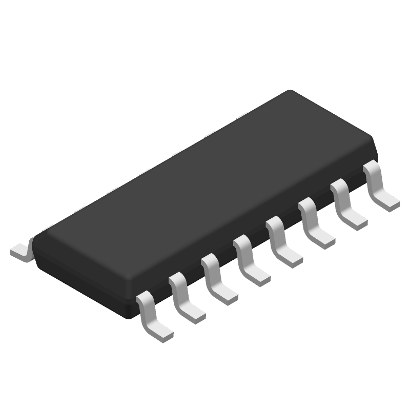
Footprint
-
3D Model
Available Download Formats
By downloading CAD models, you agree to our Terms & Conditions and Privacy Policy

20-V, 2:1 (SPDT), 3-channel analog multiplexer with logic-level conversion 16-SOIC -55 to 125
Tip: Data for a part may vary between manufacturers. You can filter for manufacturers on the top of the page next to the part image and part number.
CD4053BMG4 by Texas Instruments is a Multiplexer or Switch.
Multiplexers or Switches are under the broader part category of Signal Circuits.
A signal is an electronic means of transmitting information, either as an analog signal with continuous values or a digital signal with discrete values. Signals are used in various systems and networks. Read more about Signal Circuits on our Signal Circuits part category page.
| Part # | Distributor | Description | Stock | Price | Buy | |
|---|---|---|---|---|---|---|
|
|
Quest Components | TRIPLE 2-CHANNEL, SGL ENDED MULTIPLEXER, PDSO16 | 3 |
|
$1.0644 | Buy Now |
By downloading CAD models, you agree to our Terms & Conditions and Privacy Policy
|
|
CD4053BMG4
Texas Instruments
Buy Now
Datasheet
|
Compare Parts:
CD4053BMG4
Texas Instruments
20-V, 2:1 (SPDT), 3-channel analog multiplexer with logic-level conversion 16-SOIC -55 to 125
|
| Pbfree Code | Yes | |
| Rohs Code | Yes | |
| Part Life Cycle Code | Obsolete | |
| Ihs Manufacturer | TEXAS INSTRUMENTS INC | |
| Part Package Code | SOIC | |
| Package Description | GREEN, PLASTIC, MS-012AC, SOIC-16 | |
| Pin Count | 16 | |
| Reach Compliance Code | compliant | |
| HTS Code | 8542.39.00.01 | |
| Samacsys Manufacturer | Texas Instruments | |
| Analog IC - Other Type | SINGLE-ENDED MULTIPLEXER | |
| Bandwidth-Nom | 30 MHz | |
| Input Voltage-Max | 20.5 V | |
| Input Voltage-Min | -0.5 V | |
| JESD-30 Code | R-PDSO-G16 | |
| JESD-609 Code | e4 | |
| Length | 9.9 mm | |
| Moisture Sensitivity Level | 1 | |
| Neg Supply Voltage-Nom (Vsup) | -5 V | |
| Normal Position | NC | |
| Number of Channels | 3 | |
| Number of Functions | 3 | |
| Number of Terminals | 16 | |
| Off-state Isolation-Nom | 40 dB | |
| On-state Resistance Match-Nom | 15 Ω | |
| On-state Resistance-Max (Ron) | 1050 Ω | |
| Operating Temperature-Max | 125 °C | |
| Operating Temperature-Min | -55 °C | |
| Output | COMMON OUTPUT | |
| Package Body Material | PLASTIC/EPOXY | |
| Package Code | SOP | |
| Package Equivalence Code | SOP16,.25 | |
| Package Shape | RECTANGULAR | |
| Package Style | SMALL OUTLINE | |
| Peak Reflow Temperature (Cel) | 260 | |
| Qualification Status | Not Qualified | |
| Seated Height-Max | 1.75 mm | |
| Supply Voltage-Max (Vsup) | 20 V | |
| Supply Voltage-Min (Vsup) | 3 V | |
| Supply Voltage-Nom (Vsup) | 5 V | |
| Surface Mount | YES | |
| Switch-off Time-Max | 720 ns | |
| Switch-on Time-Max | 720 ns | |
| Switching | BREAK-BEFORE-MAKE | |
| Technology | CMOS | |
| Temperature Grade | MILITARY | |
| Terminal Finish | Nickel/Palladium/Gold (Ni/Pd/Au) | |
| Terminal Form | GULL WING | |
| Terminal Pitch | 1.27 mm | |
| Terminal Position | DUAL | |
| Time@Peak Reflow Temperature-Max (s) | NOT SPECIFIED | |
| Width | 3.9 mm |
The maximum operating frequency of the CD4053BMG4 is typically around 10 MHz, but it can vary depending on the specific application and operating conditions. It's recommended to consult the datasheet and application notes for more information.
To ensure proper power sequencing, it's recommended to power up the VCC pin before the analog signal inputs, and to power down the VCC pin after the analog signal inputs. This helps to prevent latch-up and damage to the device.
For optimal performance, it's recommended to follow good analog layout and routing practices, such as keeping the analog signal paths short and away from digital signals, using a solid ground plane, and minimizing parasitic capacitance and inductance.
The CD4053BMG4 has built-in ESD protection, but it's still recommended to follow proper ESD handling procedures when handling the device, such as using an ESD wrist strap or mat, and storing the device in an ESD-safe environment.
The thermal resistance of the CD4053BMG4 package (QFN-16) is typically around 30-40°C/W, depending on the specific application and operating conditions. This information can be found in the datasheet or by consulting with Texas Instruments support.