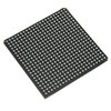
Part Details for 82P20516DBFG by Integrated Device Technology Inc
Results Overview of 82P20516DBFG by Integrated Device Technology Inc
- Distributor Offerings: (0 listings)
- Number of FFF Equivalents: (0 replacements)
- CAD Models: (Request Part)
- Number of Functional Equivalents: (0 options)
- Part Data Attributes: (Available)
- Reference Designs: (Not Available)
Tip: Data for a part may vary between manufacturers. You can filter for manufacturers on the top of the page next to the part image and part number.
82P20516DBFG Information
82P20516DBFG by Integrated Device Technology Inc is a Digital Transmission Interface.
Digital Transmission Interfaces are under the broader part category of Telecommunication Circuits.
A telecommunications circuit transmits and receives information between points. Key components include transmitters, receivers, amplifiers, and multiplexers. Read more about Telecommunication Circuits on our Telecommunication Circuits part category page.
Part Details for 82P20516DBFG
82P20516DBFG CAD Models
82P20516DBFG Part Data Attributes
|
|
82P20516DBFG
Integrated Device Technology Inc
Buy Now
Datasheet
|
Compare Parts:
82P20516DBFG
Integrated Device Technology Inc
CABGA-484, Tray
|
| Pbfree Code | Yes | |
| Rohs Code | Yes | |
| Part Life Cycle Code | Transferred | |
| Ihs Manufacturer | INTEGRATED DEVICE TECHNOLOGY INC | |
| Part Package Code | CABGA | |
| Package Description | FPBGA-484 | |
| Pin Count | 484 | |
| Manufacturer Package Code | BFG484 | |
| Reach Compliance Code | compliant | |
| ECCN Code | EAR99 | |
| HTS Code | 8542.39.00.01 | |
| JESD-30 Code | S-PBGA-B484 | |
| JESD-609 Code | e1 | |
| Moisture Sensitivity Level | 3 | |
| Number of Functions | 1 | |
| Number of Terminals | 484 | |
| Operating Temperature-Max | 85 °C | |
| Operating Temperature-Min | -40 °C | |
| Package Body Material | PLASTIC/EPOXY | |
| Package Code | BGA | |
| Package Equivalence Code | BGA484,22X22,32 | |
| Package Shape | SQUARE | |
| Package Style | GRID ARRAY | |
| Peak Reflow Temperature (Cel) | 260 | |
| Qualification Status | Not Qualified | |
| Supply Voltage-Nom | 1.8 V | |
| Surface Mount | YES | |
| Telecom IC Type | PCM TRANSCEIVER | |
| Temperature Grade | INDUSTRIAL | |
| Terminal Finish | TIN SILVER COPPER | |
| Terminal Form | BALL | |
| Terminal Pitch | 0.8 mm | |
| Terminal Position | BOTTOM | |
| Time@Peak Reflow Temperature-Max (s) | 30 |
82P20516DBFG Frequently Asked Questions (FAQ)
-
A good PCB layout for the 82P20516DBFG should prioritize signal integrity, minimize noise, and ensure proper power supply decoupling. IDT recommends using a 4-layer PCB with a solid ground plane, and placing the device near the center of the board. Additionally, use short, direct traces for clock and data signals, and avoid routing them near the power supply or noisy areas.
-
To ensure reliable operation of the 82P20516DBFG in high-temperature environments, follow proper thermal management practices. Ensure good airflow around the device, and consider using a heat sink or thermal interface material if necessary. Also, operate the device within its specified temperature range (–40°C to +85°C) and avoid exceeding the maximum junction temperature (150°C).
-
The recommended termination resistors for the 82P20516DBFG's differential pairs depend on the specific application and signal frequency. As a general guideline, use 100-ohm differential termination resistors for PCIe Gen1 and Gen2, and 85-ohm resistors for PCIe Gen3. However, consult the specific application requirements and IDT's documentation for more detailed guidance.
-
To troubleshoot issues with the 82P20516DBFG's PCIe interface, start by verifying the device's power supply and clock signals. Check for proper signal integrity, and ensure that the device is properly configured and initialized. Use tools like PCIe analyzers or logic analyzers to capture and analyze the PCIe traffic, and consult IDT's documentation and application notes for guidance on specific error scenarios.
-
While the 82P20516DBFG is primarily designed for PCIe applications, it can be used in non-PCIe applications with some limitations. However, this may require custom configuration and programming of the device. Consult IDT's documentation and application notes for guidance on using the device in non-PCIe applications, and be aware of potential limitations and trade-offs in terms of performance, power consumption, and functionality.
