-
Part Symbol
-
Footprint
-
3D Model
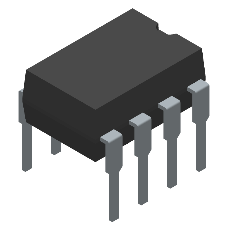
Available Download Formats
By downloading CAD models, you agree to our Terms & Conditions and Privacy Policy
Optocoupler - IC Output, 1 CHANNEL LOGIC OUTPUT OPTOCOUPLER, 0.1 Mbps, 11-10C4, 8 PIN
Tip: Data for a part may vary between manufacturers. You can filter for manufacturers on the top of the page next to the part image and part number.
6N139 by Toshiba America Electronic Components is an Optocoupler.
Optocoupler are under the broader part category of Optoelectronics.
Optoelectronic components work to detect, generate, and control light. They can essentially produce and/or react to light. Read more about Optoelectronics on our Optoelectronics part category page.
| Part # | Distributor | Description | Stock | Price | Buy | |
|---|---|---|---|---|---|---|
|
|
Bristol Electronics | 239 |
|
RFQ | ||
|
|
Quest Components | DARLINGTON-NPN-OUTPUT DC-INPUT OPTOCOUPLER,1-CHANNEL,2.5KV ISOLATION,DIP | 120 |
|
$0.6250 / $1.2500 | Buy Now |
|
|
Chip 1 Exchange | INSTOCK | 4756 |
|
RFQ |
By downloading CAD models, you agree to our Terms & Conditions and Privacy Policy
|
|
6N139
Toshiba America Electronic Components
Buy Now
Datasheet
|
Compare Parts:
6N139
Toshiba America Electronic Components
Optocoupler - IC Output, 1 CHANNEL LOGIC OUTPUT OPTOCOUPLER, 0.1 Mbps, 11-10C4, 8 PIN
|
| Part Life Cycle Code | Obsolete | |
| Ihs Manufacturer | TOSHIBA CORP | |
| Package Description | 11-10C4, 8 PIN | |
| Reach Compliance Code | unknown | |
| HTS Code | 8541.40.80.00 | |
| Samacsys Manufacturer | Toshiba | |
| Additional Feature | UL RECOGNIZED, CMOS COMPATIBLE | |
| Configuration | SINGLE | |
| Current Transfer Ratio-Min | 400% | |
| Data Rate-Nom | 0.1 MBps | |
| Forward Current-Max | 0.02 A | |
| Forward Voltage-Max | 1.7 V | |
| Isolation Voltage-Max | 2500 V | |
| Mounting Feature | THROUGH HOLE MOUNT | |
| Number of Elements | 1 | |
| Number of Functions | 1 | |
| On-State Current-Max | 0.06 A | |
| Operating Temperature-Max | 70 °C | |
| Operating Temperature-Min | ||
| Optoelectronic Device Type | LOGIC IC OUTPUT OPTOCOUPLER | |
| Power Dissipation-Max | 0.1 W | |
| Response Time-Max | 0.000025 s | |
| Surface Mount | NO |
This table gives cross-reference parts and alternative options found for 6N139. The Form Fit Function (FFF) tab will give you the options that are more likely to serve as direct pin-to-pin alternates or drop-in parts. The Functional Equivalents tab will give you options that are likely to match the same function of 6N139, but it may not fit your design. Always verify details of parts you are evaluating, as these parts are offered as suggestions for what you are looking for and are not guaranteed.
| Part Number | Manufacturer | Composite Price | Description | Compare |
|---|---|---|---|---|
| 6N139VM | Fairchild Semiconductor Corporation | Check for Price | 8-Pin DIP Single-Channel Low Input Current High Gain Split Darlington Output Optocoupler, 8LD,MDIP,.300" WIDE, OPTO, WHITE, 1000/BULK | 6N139 vs 6N139VM |
| 6N139 | Siemens | Check for Price | Logic IC Output Optocoupler, 1-Element, 2500V Isolation, PLASTIC, DIP-8 | 6N139 vs 6N139 |
| 6N139 | Fairchild Semiconductor Corporation | Check for Price | Logic IC Output Optocoupler, 1-Element, 2500V Isolation, DIP-6 | 6N139 vs 6N139 |
| 6N139 | onsemi | Check for Price | Logic IC Output Optocoupler | 6N139 vs 6N139 |
The maximum allowable voltage that can be applied to the input pins is 5V, exceeding which may cause damage to the device.
To ensure reliability in high-temperature applications, it is recommended to derate the device's current and voltage ratings according to the temperature derating curve provided in the datasheet.
The recommended layout and spacing for the 6N139 on a PCB is to keep the input and output circuits separate, with a minimum spacing of 1.5 mm between them, and to use a ground plane to minimize electromagnetic interference.
The 6N139 is not suitable for high-frequency applications above 1 MHz due to its limited bandwidth. For high-frequency applications, a different optocoupler with a higher bandwidth should be considered.
To troubleshoot issues with the 6N139, check the input voltage and current, ensure proper PCB layout and spacing, and verify that the device is operated within its recommended ratings. If issues persist, consult the datasheet or contact Toshiba's technical support.